Pulsafeeder PulsaPro 900 EN User Manual
Page 50
46
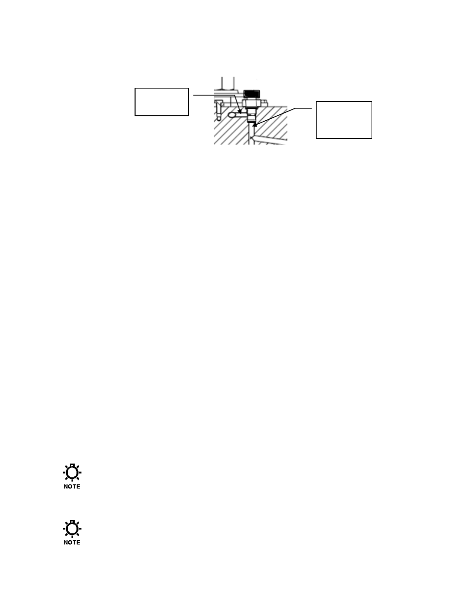
12. If the pump is not already hydraulically primed, remove the PTP valve from the top of the
pump head. Using a plastic funnel or similar, slowly pour hydraulic fluid into the pump head
cavity until full. The end of the funnel should fit into the small diameter hole at the bottom of
the PTP socket – not the larger threaded diameter. The threaded diameter includes a side
drain passage that will prevent oil from entering the pump head if used. Alternatively apply a
vacuum to the bottom hole of the PTP socket to draw oil from the makeup valve.
13. Inspect the PTP valve to ensure the sealing o-ring and copper gasket are still in position, and
re-install the valve.
14. In order to fully balance and evacuate the leak detection system, the pump must now run at
normal discharge pressure for a period of one hour. This ensures that excess barrier fluid is
fully evacuated from the system.
15. Supply either process fluid, or test fluid (i.e. water) to the suction of the pump and ensure that
the discharge system is configured for safe operation. The pump can be started with minimal
discharge pressure and then slowly brought up to full pressure, if the system allows for this.
16. Apply power and start the pump.
17. Adjust the pump slowly to full (100%) stroke.
18. Hold down the PTP valve momentarily and observe the smaller tube under the diagnostic
cover. If no fluid is coming from this port after 5 minutes, stop the pump and return to step
11. If fluid is present, continue to step 19.
19. Slowly increase the discharge pressure to full operating pressure, and continue to run the
pump for a period of one hour.
20. During this time, excess barrier fluid will be displaced from the system into the short length
of tubing attached to the exit port, balancing the system for proper operation. A small pen
mark on the tube can assist in observing this process visually.
21. After the one-hour startup period, remove the tubing and connection from the housing body
and reinstall the pressure gage. Remove the fitting from the fill port and replace with the
supplied pipe plug.
22. Reconnect the alarm switch to the external system if necessary.
23. The pump and pressure leak-detection system are now properly prepared and ready for
normal service. During normal operation, the gauge should roughly indicate 0 (zero)
pressure.
Under certain circumstances, the system may not completely evacuate excess barrier fluid
during the procedure as outlined above. In these cases, after several days run time, a
small amount of pressure may build in the system. If this occurs, simply loosen the
pressure gauge from the switch housing and relieve a small amount of barrier fluid,
returning the system to a zero-pressure state.
Once this startup procedure is completed, the pressure leak detection system should
require no further maintenance.
Drain
Passage
Funnel
should
enter here