Draft 1 – Aastra Telecom 9480i Series User Manual
Page 1020
Troubleshooting Parameters
A-246
41-001160-03, Rev 00, Release 2.4
IP Phone Administrator Guide
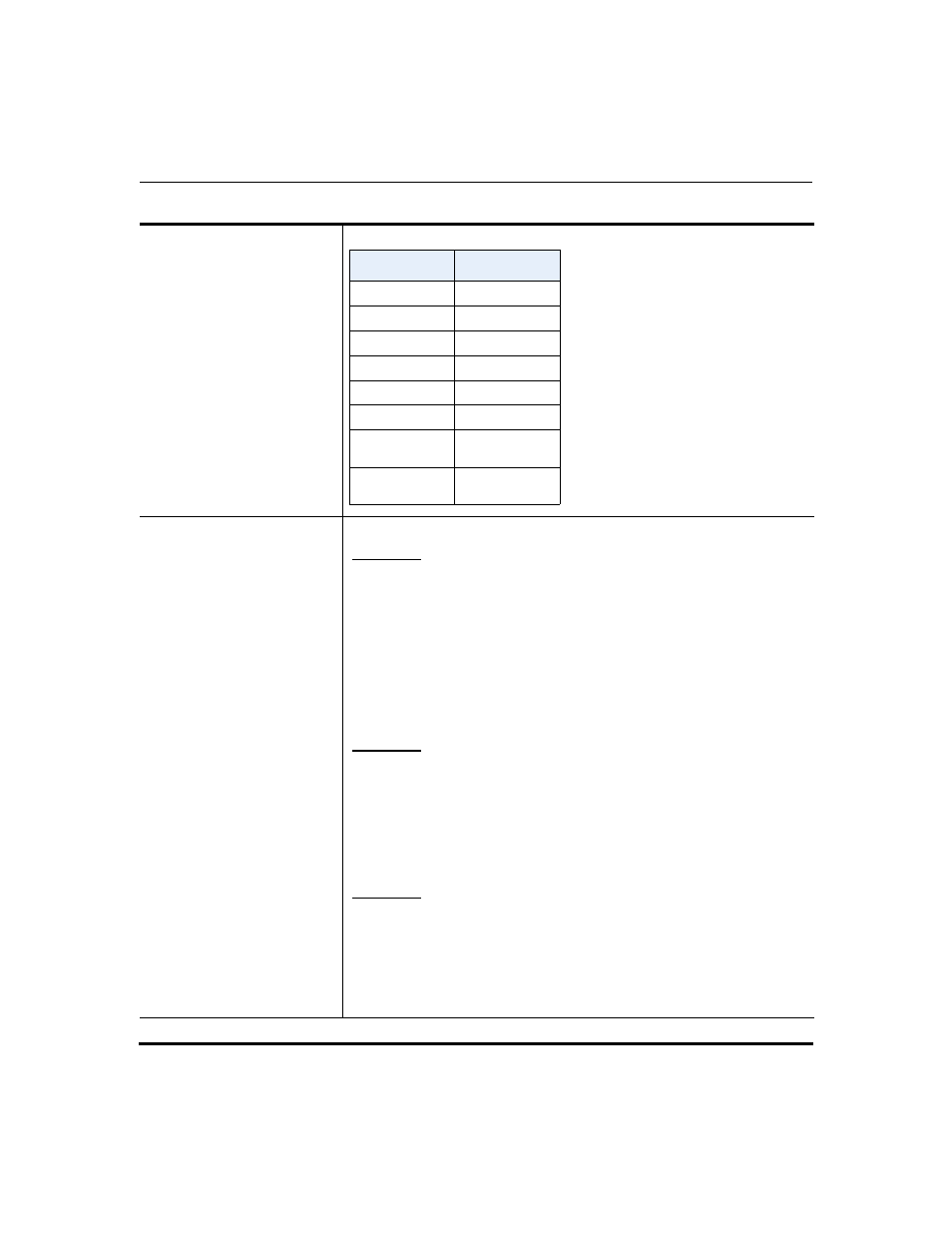
Range
Examples
Enter a debug level value in the “Debug Level” field for a module.
Example 1
To turn two or more debug levels on at the same time, you add the value
associated with each level. For example,
Fatal Errors + Errors + Warnings = 1 + 2 + 4 = 7
log module linemgr: 7
log module user interface: 7
log module sip: 7
In the above example, fatal errors, general errors, and warnings are
logged for the line manager, user interface, and SIP call control modules.
Example 2
Functions and Info = 16 + 32 = 48
log module dis: 48
log module net: 48
log module snd: 48
In the above example, functions and general information are logged for
the display drivers, network, and sound modules.
Example 3
log module rtpt: 0
log module ind: 65535
In the above example, all debug levels are OFF for the Real Time
Transport module. All debug levels are ON for the indicator module.
You can set the Module/Debug Levels using the configuration files or the
Aastra Web UI.
Debug Level
Value
Fatal Errors
1 (default)
Errors
2
Warnings
4
Init
8
Functions
16
Info
32
All debug
levels OFF
0
All Debug
Levels ON
65535
Draft 1