Quick view, Chapter 1 — quick start, Asantébridge 1012 front panel – Asante Technologies 1012 User Manual
Page 18: Page 1-6
Page 1-6
Chapter 1 — Quick Start
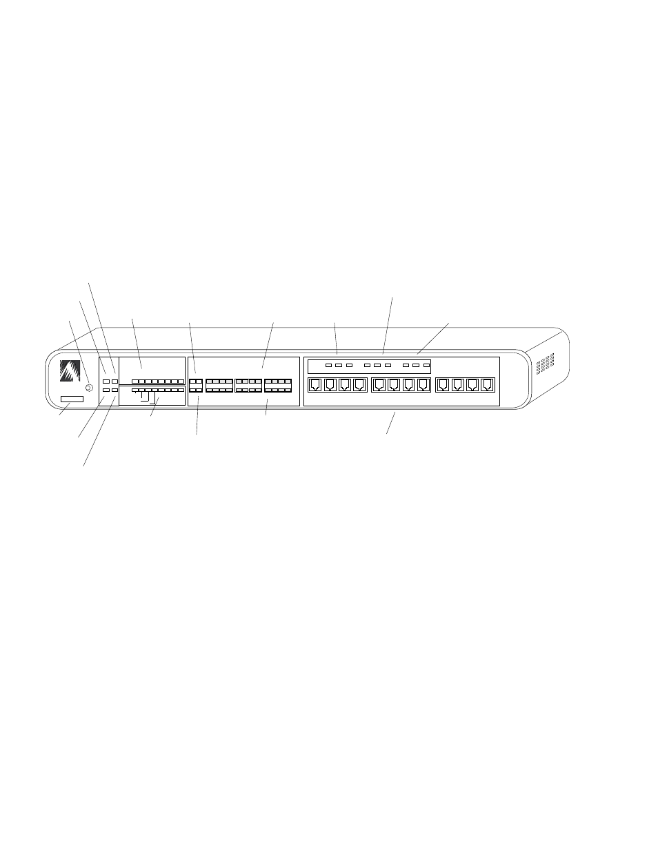
Before you install the AsantéBridge 1012, you should become
familiar with both the front and rear panels. The following illustra-
tions show the front and rear panels. Sit down in front of your
unit and find each of the items shown in the illustrations, then
locate the item in the following text.
Look at the AsantéBridge front panel as shown in Figure 1-3. All
controls and indicators are labeled with a brief definition.
Figure 1-3 AsantéBridge 1012 Front Panel
Physical Address
This is the physical address of this AsantéBridge 1012; preset at
the factory and cannot be modified.
Reset button
Allows you to reset all bridge and hub software. Any packets
currently buffered are lost. When the bridge resets, power on
diagnostics run automatically. The power LED goes off momen-
tarily when the diagnostics run.
Power LED
Lights when the AsantéBridge 1012 is turned on.
CPU Activity LED
This LED flashes when bridge or hub activity occurs; if the LED
remains off, a hardware problem exists.
Quick View
AsantéBridge 1012
Front Panel
ASANTE
RESET
PWR
CPU
SNMP MSG
UTILIZATION
%
PARTITION
LINK/RECEIVE
BRDG
1
1
10BASE-T PORTS
AsantéHub 1012
1
3
5
10
20
30
50
65+
UPLINK
2
3
4
5
6
7
8
9
10
11
12
2
3
4
5
6
7
8
9
10
11
12
COLLISION
%
1
3
5
10+
Late Collision
Misaligned CRC
Runts/Fragments
Short Event/Missing SFD
STATUS STANDBY ACTIVE
RCV
FWD
COL
BRIDGE
RCV
FWD
COL
BRIDGE
0000944007B3
EXT PORT
HUB
Reset
Button
Physical
Address
Power LED
CPU Activity
LED
SNMP Agent
Activity
MSG LED
Hub Status LEDs
Hub Utilization
LEDs
Uplink
Partition LED
Port
Partition LEDs
Port Link/Receive LEDs
Bridge/Uplink Link/Receive LEDs
Bridge External
Port Status LEDs
Bridge Spanning Tree
Status LEDs
Bridge Hub
Port Status LEDs
RJ45 Port Connectors