1 internal tamper disable jumpers, 2 relay jumpers, 3 tamper (reader interface board) – HID EDGE EVO EH400-K Standard Controller Installation Guide User Manual
Page 7: Standard networked controller, 1 internal optical tamper
82000-921 C.0
INSTALLATION GUIDE
7
©2009 - 2011 HID Global Corporation. All rights reserved.
Standard Networked Controller
EH400-K
3.1 Internal Optical Tamper
To disable the internal optical tamper sensor for the right side PCB (reader interface board), attach a jumper wire from
P3 pin 10 to P3 pin 5.
To disable the internal optical tamper sensor for the left side PCB (door interface board), attach a jumper wire from P3
pin 1 to P3 pin 2.
CAUTION: The EH400-K ships from HID with these jumpers pre-installed on the connectors. Removing
these jumpers causes false tampers to trigger.
Note:
If desiring an external tamper, wire an unsupervised Normally Closed contact, replacing one of
the pre-installed jumpers.
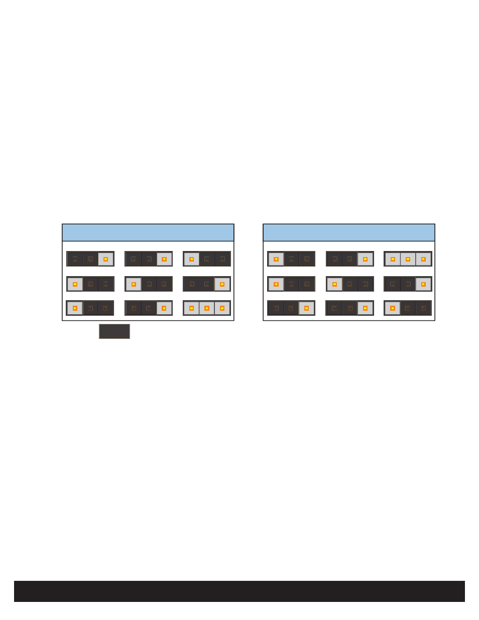
3.2 Relay Jumpers
AUX Wet
CAN V+
AUX Wet
+12VDC
AUX Dry
DS Wet
CAN V+
DS Wet
+12VDC
DS Dry
3
1
P9
P5
P8
3
1
3
1
3
1
P6
P4
P7
3
1
3
1
JUMPER =
3.3 Tamper (Reader Interface Board)
The Reader Tamper + and - are implemented allowing a connection for an open collector external tamper from a
reader, such as iCLASS.
Note: Connect P3, Pin 12 (GND) from the Reader Interface Board to the same ground as the reader power, if the
reader is not powered by the units 12 VDC output port.