1 - power analysis, Step 1 - identify system components, Step 2 - create system layout – HID EDGE EVO EH400-K Standard Controller Installation Guide User Manual
Page 2: Power analysis, Standard networked controller
Standard Networked Controller
EH400-K
82000-921 C.0
INSTALLATION GUIDE
2
©2009 - 2011 HID Global Corporation. All rights reserved.
Before starting installation, determine which components will be used in the system and analyze the power requirements to avoid
over-loading the EDGE EVO Hi-O Networked Controller & Reader (EH400-K).
The steps that follow illustrate sizing power requirements for the system.
Step 1 - Identify System Components
Identify the components that will be used in the system. A typical installation may include the following components:
•
Door Position Switch – Detects when the door is open or closed.
•
Magnetic Lock – Holds the door locked.
•
Request to Exit (REX) Switch – Unlocks the door when exiting the secured area.
•
EDGE EVO Hi-O Standard Networked Controller (EH400-K) – Provides access control and manages all
peripherals around the door.
•
iCLASS Wiegand Reader – Provides entry into the secured area.
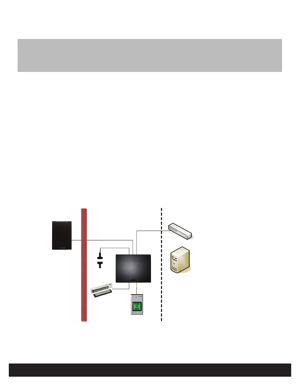
Step 2 - Create System Layout
Using the components identified in “Step 1 - Identify System Components” on page 2, create the system layout.
In this example, the EH400-K is connected to the remote server through an Ethernet connection and manages door
peripherals over the Hi-O bus. Controlling downstream door peripherals, the EH400-K is a fully integrated single-door
controller offering discrete I/O and Wiegand/Clock-and-Data interfaces to external readers. The EH400-K receives inputs
from the Door Position Switch and REX Switch to drive the Magnetic Lock output.
Unprotected
Area
Protected Area
Physical Access
Control Server
(real-time functions
not required )
Remote Area
Wiegand
Ethernet Switch
Ethernet Data
Door Position
Switch
Magnetic Lock
REX Switch
Wiegan
Door P
Swi
Mag
cted
ne
Wiegand Reader
EH400-K
Figure 1 - System Layout Example
1
Power Analysis