American Power Conversion 10-30 KVA User Manual
Page 17
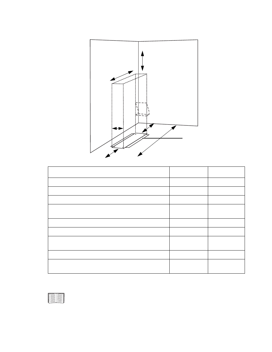
Site Preparation – Installation Space Requirements
990-1598B
Smart-UPS® VT 10-30 kVA, 208/220 V Site Preparation and Installation Manual
11
Clearance for stand-alone 13.85 in/352 mm Enclosures
*) Minimum free rear space for ventilation 4 in/100 mm.
Space requirements
in
mm
Minimum clearance above UPS (A)
20.00
508
UPS depth (B)
32.99
854
UPS width
13.85
352
Minimum rear service clearance* (compliant with NEC 110.26
for North America) (D)
36.00
914
Minimum front clearance (E)
40.00
1,000
Conduit Box, depth (F)
3.46
88
No side clearance required (add width of Stabilizing Bracket for
floor anchoring if applicable)
0
0
Stabilizing Bracket width
3.34
85
Total installation depth, inclusive of Front Panel, Conduit Box
and minimum front and rear clearances (G)
112.45
2.840
For the stability of 13.85 in/352 mm stand-alone Enclosures, the Stabilizing Brackets
must always be mounted on both sides of the UPS. See Stabilizing Brackets.
(C)
(A)
(D)
Stabilizing Bracket,
left and right
UPS
Conduit Box (F)
(B)
(G)
(E)