Installation and start-up – Blodgett SN-G Series User Manual
Page 11
OM-SN-G 9
Installation and Start-Up
5.
Factory Stacked Units
This section is applicable only if you are installing factory-stacked units.
Installing stacked steamers is similar to installing a single unit. The steamers
are stacked and assembled at the factory and delivered with the water
connections and drain hoses required for a single point connection.
a.
Water Connection
The same water supply connection is used for both units. At the water
inlet valves, 3⁄4 inch female NH connectors (garden hose type) are
used for the water supplies. There are two connections to be made.
Treated water (softened) is connected to the right valve fitting (looking
from the rear of the unit) and untreated water to the left fitting.
b.
Electrical Supply Connection
Separate, individual electrical connections will be required for each
steamer in the stack. Each Steamer must have its own branch circuit
protection.
c.
Gas Connection
Separate gas connections are required for each steamer in the stack.
Gas supply must be adequate under all conditions as listed on page 9.
d.
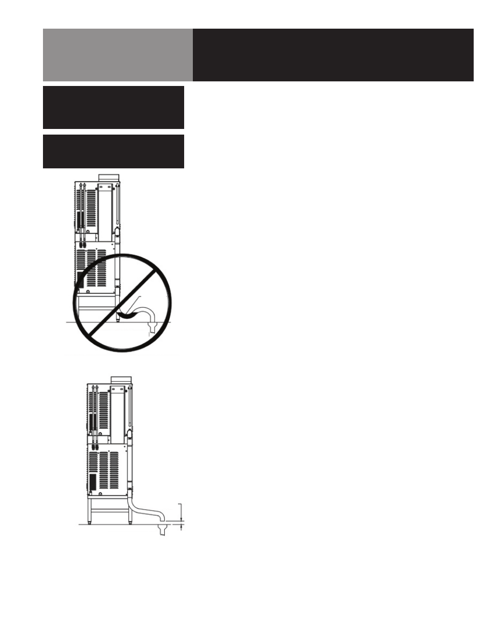
Drain Connection
Steamers must be leveled front to back, or pitched to the rear
(maximum 1⁄4 inch) by adjusting the bullet feet on the stand. A 2 inch
ID hose may be attached to the unit drain. It must be rated for very hot
water.
Ensure that there is a free air gap between the end of the unit drain
and the building drain. This gap should be as close as possible to the
unit drain. Do not allow elbows or restrictions between the unit and the
free air gap.
Install the line with a constant downward pitch.
CAUTION
DO NOT USE PLASTIC PIPE. DRAIN MUST
BE RATED FOR VERY HOT WATER.
WARNING
DO NOT CONNECT THE DRAIN DIRECTLY
TO A BUILDING DRAIN. BLOCKING THE
DRAIN IS HAZARDOUS.
WATER
TRAP
BUILDING DRAIN
IMPROPER DRAIN LINE CONNECTION
PROPER DRAIN LINE CONNECTION
BUILDING DRAIN
AIR GAP
Proper Drain Line Connection:
Drain line must have a constant down-
ward pitch of at least 1/4” per foot.