Installation and start-up – Blodgett SN-G Series User Manual
Page 10
8
OM-SN-G
2.
Gas Supply Connection
Connection to the gas supply can be completed with 1⁄2” NPT pipe
or approved equivalent. Although the immediate connection to the
appliance is 1⁄2” NPT, gas supply piping must be large enough to provide
62,000 BTU/hr/cavity. Supply pressure must be at least 4.5” W.C.
(maximum 14” W.C.) for natural gas or 12” W.C. (maximum 14” W.C.) for
LP gas. In Canada, the installation must conform to the Canadian Gas
Code, CAN 1-B149, Installation Codes for Gas Burning Appliances and
Equipment and/or local codes. Check all gas connections for leaks prior
to unit operation.
After the unit has been connected to the gas supply, all gas joints must
be checked for leaks. No flame should be used when checking for leaks.
A thick soap solution or other suitable leak detector should be used.
For a unit on casters, complete connection to the gas supply with
connectors that comply with the standard for connectors for moveable
gas appliances, ANSI Z21.69 — latest edition. Restrain movement of the
unit by attaching a cable or chain to the eyelet (provided at the back of
the frame) and anchoring the cable or chain to the wall or floor. Make the
length and location of the cable such that the unit cannot pull on the gas
connection while the cable is connected.
3.
Water Connection(s)
Install a check valve to prevent back flow in the incoming cold water line,
as required by local plumbing codes. Water pressure in the line should
be between 30 and 60 PSIG and must deliver a flow rate of 1.5 to 3.0
gallons per minute. If pressure is above 60 PSIG, a pressure regulator will
be needed.
3⁄4 inch female NH connectors (garden hose type) are used to attach the
water supply to the inlet valves. One connector is for the steam generator
(treated), the other is for the spray condenser (untreated).
Minimum
inside diameter of the water feed line is 1⁄2 inch. Use a washer in
the hose connection. Do not allow the connection to leak, no matter how
slowly. Do not over tighten hose connections. Treated (softened) water
goes to the right (seen from the rear of the unit), and untreated water to
the left. Connections for both are made as shown on Page 7. Though not
recommended, an adapter to use a single water intake is available.
4.
Drain Connection
Level the steamer front to back, or pitch it slightly to the rear (maximum
1⁄4 inch) by adjusting the optional legs or bullet feet on optional stand. A
2 inch ID hose may be attached to the drain pipe (supplied). There must
be a free air gap between the end of the hose and the building drain. The
free air gap should be as close as possible to the unit drain. There must
also be no other elbows or other restrictions between the unit drain and
the free air gap.
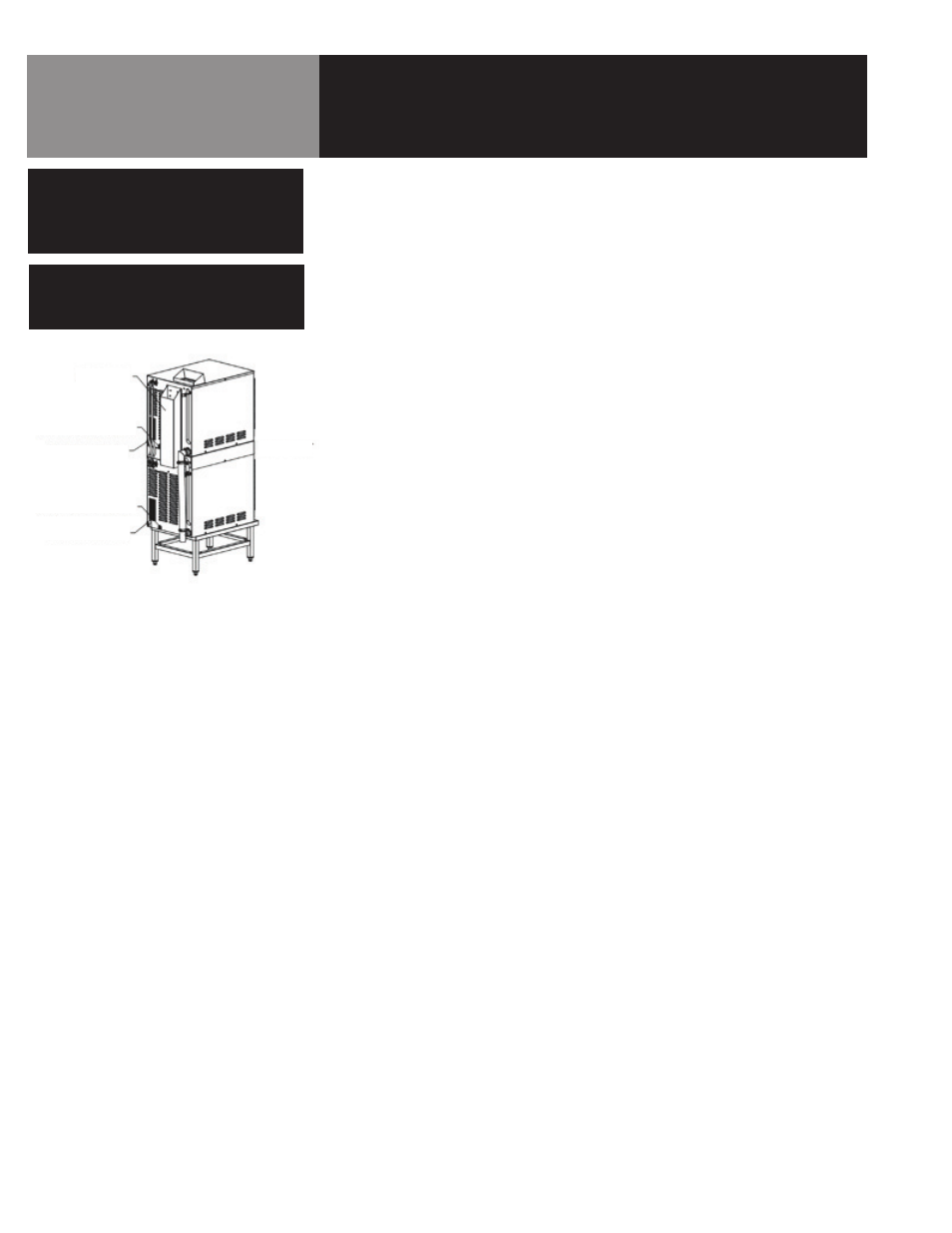
Installation and Start-Up
REAR FLUE
UNIT FRONT
ELECTRICAL OPENING
ELECTRICAL OPENING
GAS CONNECTION
GAS CONNECTION
CAUTION
DO NOT USE PLASTIC PIPE. DRAIN MUST
BE RATED FOR VERY HOT WATER.
WARNING
DO NOT CONNECT THE DRAIN DIRECTLY
TO A BUILDING DRAIN. BLOCKING THE
DRAIN IS HAZARDOUS.
Install the drain line
with a constant downward pitch.
IMPORTANT: Do not allow water traps in the line.
A trap can cause pressure build-up in the cavity,
which may cause the door gasket to leak.