A106, Assembly & installation instructions – Hubbardton Forge 126501 User Manual
Page 2
If you need further assistance, or find that you are missing any parts, please contact the dealer from which you purchased this product.
We hope you enjoy your fixture!
* Hubbardton Forge will not be liable for injury or damage caused by improper installation, lamping or use of this fixture.
H U B B A R D T O N F O R G E . C O M
hand-forged, vermont-made lighting and accessories
154 RT. 30 SOUTH
•
CASTLETON, VERMONT 05735
All designs and images ©1989-2013 Hubbardton Forge
®
. All rights reserved.
19777 Rev A
Assembly & Installation Instructions
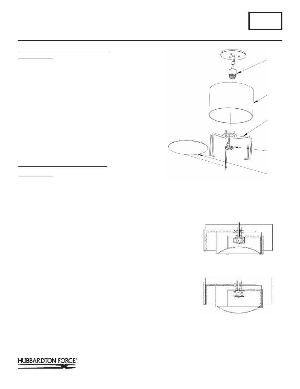
To Install Shade and Glass for 12-6498
(Figure 2)
Component Parts
F Socket Assembly
G Shade
H Spider Assembly
I Retaining Ring
J Diffuser
1. Place Shade (G) into notches of spider assembly (H).
2. Lift shade (G) and spider assembly (H) over socket assem-
bly (F) until it stops.
3. Thread retaining ring (I) on socket until snug against spider
assembly (H).
4. Slip Glass Diffuser (J), curved side up, at an angle into spi-
der assembly (H) and rotate to rest on the arms. It may be
necessary to flex on support arm slightly to install diffuser.
See Figure 2A for correct orientation of diffuser.
To Install Shade and Glass for 12-6501
(Figure 3)
Component Parts
K Socket Assembly
L Inner Shade
M Inner Spider Assembly
N Retaining Ring
1. Place inner shade (L) into notches of inner spider assembly
(M).
2. Lower outer spider assembly (P) until it rests on top of inner
shade (L).
3. Align holes in inner spider assembly (M) and outer spider
assembly (P).
Note: Spider arms should be in six equal spaces. If arms are
aligned over top of each other turn outer spider 180 degrees to
align.
4. Install thumb screws (R) to attach inner spider assembly to
outer spider assembly.
5. Lower outer shade (Q) until it rests in the brackets of the
outer spider assembly (P).
6. Lift the assembled shade and spider assemblies over the
socket assembly (K) until it stops.
A106
For Semi-Flush Models 126498 & 126501
Page 2 of 3
(Figure 2)
F
G
H
I
J
DIFFUSER INSTALLED
CORRECTLY
DIFFUSER INSTALLED
INCORRECTLY
(Figure 2A)
O Glass Diffuser
P Outer Spider ssembly
Q Outer Shade
R Thumb Screw (2)