B134, Installation instructions – Hubbardton Forge 217651 User Manual
Page 2
Installation Instructions
B134
For Gallery Sconce 21-7651F
Page 2 of 3
Hand-Forged,
Vermont-Made Lighting and Accessories
P.O. Box 827, 154 Route 30 South, Castleton, Vermont 05735
21124
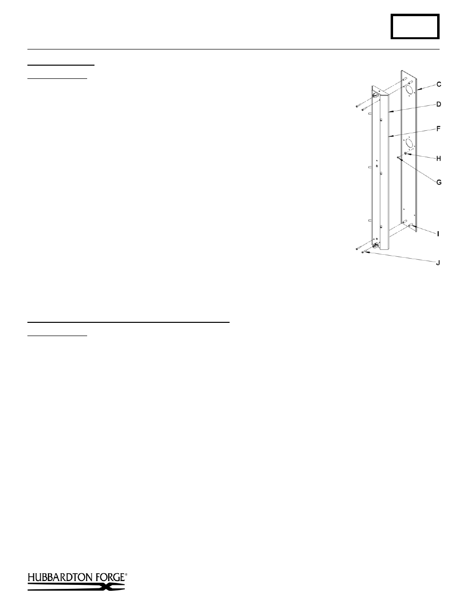
To Install Fixture
(Figure 3)
Component Parts
C Wall Mounting Bracket
F Fixture Can Assembly
G Ground
Screw
H Cupped
Washer
I
Threaded Standoff (4)
J #8 Screws (4)
1. Hold the fixture can assembly (F) close to the wall mounting bracket (C) and
using suitable wire connectors (not provided), connect fixture wires to supply
wires (white to white, black to black, and bare copper or green to bare copper or
green). Ground the mounting bracket using the ground screw (G) mounted to the
wall mounting bracket (C).
Caution: Make sure wire connectors are twisted on securely, and no bare wires
are exposed.
2. Carefully tuck all wires behind the fixture can assembly (F) and inside the wall
mounting bracket (C) and place the fixture over the bracket so the holes in the
top and bottom match the threaded standoffs (I) protruding from the wall
mounting bracket (C). Secure the fixture by threading the #8 screws (J) through
the holes in the fixture can assembly (F) and into the wall mounting bracket (B).
3.
Refer to acrylic and front mounting instructions to complete installation.
To Install Acrylic and Complete Fixture Installation
(Figures 4 & 5)
Component Parts
F Fixture Can Assembly
K Fixture Front Panel
L Acrylic
Panel
M Ball Head Screw (2)
N Magnet Assembly (6)
1. Remove protective covering from acrylic panel (L). Some colors might not have a protective covering.
2. Slide acrylic panel (L) in opening on top of fixture front panel (K). Dull side should be facing the inside of the
fixture. Slide acrylic through until it rests at bottom of fixture front panel (K). Acrylic should be approximately
1/8" below top surface when installed.
3. Install light bulb.
4. Align holes on the top and bottom of fixture front panel (K) with the holes in the top and bottom of fixture can
assembly (F). Slide the fixture front panel (K) back until it bottoms out on magnet assembly (N).
5. If magnet assemblies (N) are not touching at all points it might be necessary to adjust them out by turning them on
the threaded stud until they touch the fixture front panel (K).
6. Thread ball head screw (M) in top and bottom of fixture can assembly (F). Tighten both ball head screws (M) to
secure fixture front panel (K).
7. Restore electricity at main breaker box.
(continued)
(Figure 3)