A331, Assembly & installation instructions – Hubbardton Forge 18730 User Manual
Page 2
If you need further assistance, or find that you are missing any parts, please contact the dealer from which you purchased this product.
We hope you enjoy your fixture!
* Hubbardton Forge will not be liable for injury or damage caused by improper installation, lamping or use of this fixture.
H U B B A R D T O N F O R G E . C O M
hand-forged, vermont-made lighting and accessories
154 RT. 30 SOUTH
•
CASTLETON, VERMONT 05735
All designs and images ©1989-2013 Hubbardton Forge
®
. All rights reserved.
28299 A
Assembly & Installation Instructions
To Install the Canopy
(Figures 1 & 2)
(Continued)
5. Using two machine screws (not provided), fasten the cross-
bar (C) to the electric box.
Important: A new electric box comes with screws. When replacing
a fixture, retain the existing screws for use with the new fixture.
6. Using suitable wire connectors (not provided) connect
fixture wires to supply (white to white or ribbed and black to
black or smooth). Run a pigtail lead from crossbar ground
screw (D) to the junction box and connect all ground wires
(bare copper or green to bare copper or green)
CAUTION: MAKE SURE WIRE CONNECTORS ARE TWISTED ON
SECURELY, AND NO BARE WIRE IS EXPOSED.
7. Slide canopy (B) over threaded studs (E) and push firmly to
ceiling, making sure that no wires are pinched between
fixture canopy and ceiling. Fasten with barrel knobs (F). Be
sure studs (E) are fully seated in the barrel knobs (F).
8. Once the fixture is fastened to the ceiling, tighten the set
screw (J) in clutch (I) firmly with hex wrench provided. Only
after the set screw (J) is tight should you install the glass.
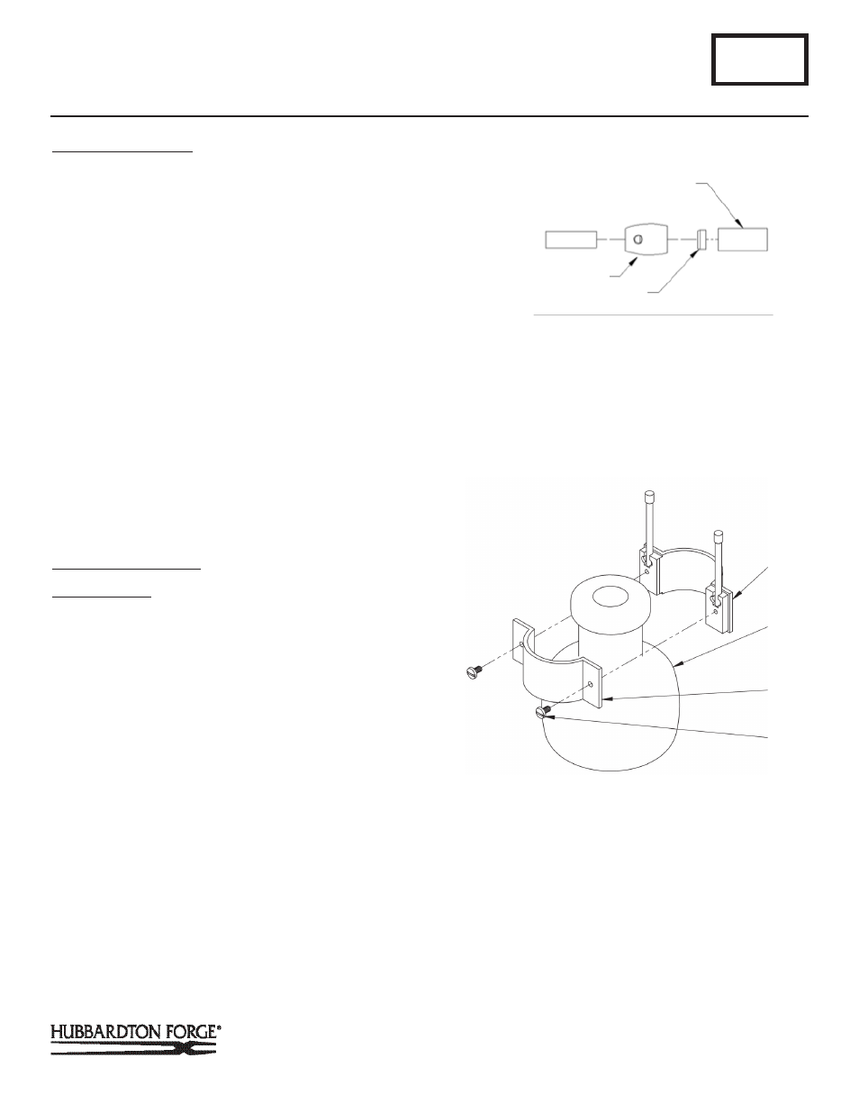
To Install Bulb & Glass
(Figures 3 & 4)
Component Parts
L Knobs (2)
M Glass Cage Half w/ Rods
N Glass Cage Half
O Screws (2)
P Bulb (Included)
Q Socket
R Glass
S Fixture Bar
1. Remove screws (O) from glass cage assembly (M & N) and
separate the two halves. Place glass (R) between cage
halves (M & N) and reattach halves using screws (O) (Figure
3).
2. Install bulb (P) into socket (Q) (Figure 4). Be careful not to
touch bulb with bare hands; oil from the hands will dramati-
cally reduce bulb life.
3. Remove knobs (L) from glass cage half with rods (M) (Figure
4).
A331
Cuff Pendant 18730 & 18733
Page 2 of 3
I
F
(Figure 3)
J
LARGE DIAMETER PIPE
CLUTCH
PLASTIC CLUTCH SLEEVE
(Figure 2)
I
(Continued)