Component parts, Continued), A275 – Hubbardton Forge 18715 User Manual
Page 2: Assembly & installation instructions
Assembly & Installation Instructions
A275
Erlenmeyer Pendant 18-710
Page 2 of 3
Hand-Forged, Vermont-Made Lighting and Accessories
154 Route 30 South, Castleton, Vermont 05735
26491
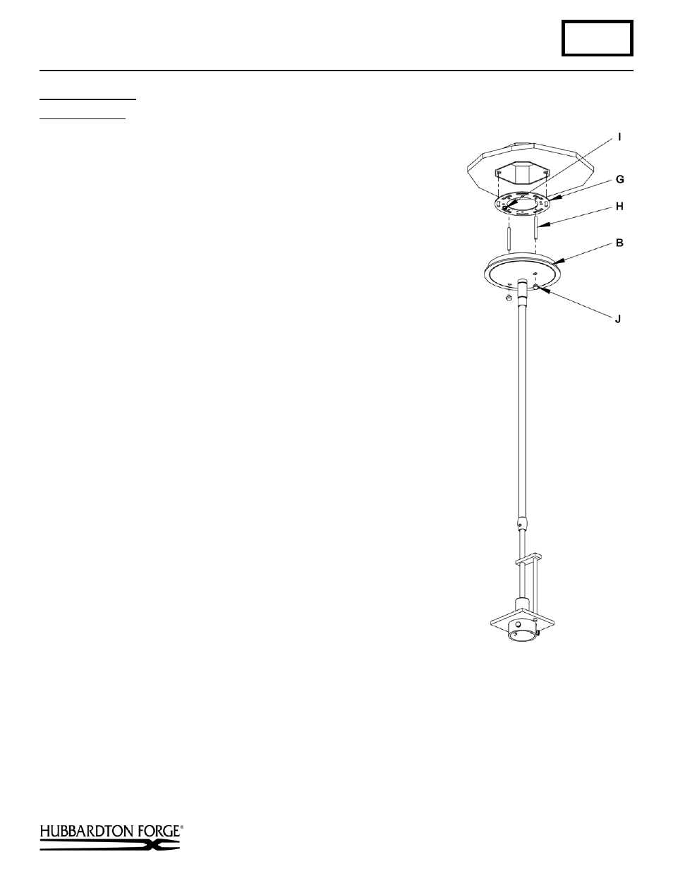
To Install Fixture
(Figure 3)
Component Parts
B Canopy
G Crossbar
H Threaded stud (2)
I
Ground screw
J
Knurled Balls (2)
Caution: Be sure power is off at the main breaker box prior to
installation.
1. Thread studs (H) through appropriate holes in the crossbar (G) to
match hole centers on canopy (B). Move ground screw (I) to
another available threaded hole if necessary.
2. Using two machine screws (not provided), fasten the crossbar (G)
to the electric box using outer oval slots to orient fixture to desired
hanging position.
Note: A new electric box comes with screws. When replacing a
fixture, retain the existing screws for use with the new fixture.
3. Using suitable wire connectors (not provided) connect fixture
wires to supply (white to white and black to black). Run a pigtail
lead from crossbar ground screw (I) to the junction box and
connect all ground wires (bare copper or green to bare copper or
green).
Caution: Make sure wire connectors are twisted on
securely, and no bare wire is exposed.
4. Slide fixture canopy (B) with fixture attached, over threaded studs
(H) and push firmly to ceiling making sure that no wires are
pinched between fixture canopy and ceiling. Fasten with the
knurled balls (J). Be sure studs (H) are fully seated in the knurled
balls (J).
Note: For sloped ceilings the notch in the swivel should face
towards the down side.
(continued)
(Figure 3)