A299, Assembly & installation instructions – Hubbardton Forge 18650 User Manual
Page 2
If you need further assistance, or find that you are missing any parts, please contact the dealer from which you purchased this product.
We hope you enjoy your fixture!
* Hubbardton Forge will not be liable for injury or damage caused by improper installation, lamping or use of this fixture.
H U B B A R D T O N F O R G E . C O M
hand-forged, vermont-made lighting and accessories
154 RT. 30 SOUTH
•
CASTLETON, VERMONT 05735
All designs and images ©1989-2013 Hubbardton Forge
®
. All rights reserved.
27145 Rev B
Assembly & Installation Instructions
Prepare the Canopy
(Figure 2)
(Continued)
3. Adjust the length of threaded nipple (E) in crossbar (D) so
that canopy ring (G) will hold canopy (F) against the ceiling
with no threads showing for best appearance. When the
correct adjustment is established, tighten jam nut
(C) against crossbar (D) to hold the adjustment.
4. Remove the crossbar (D) with stem from the electrical box
and proceed with the assembly instructions.
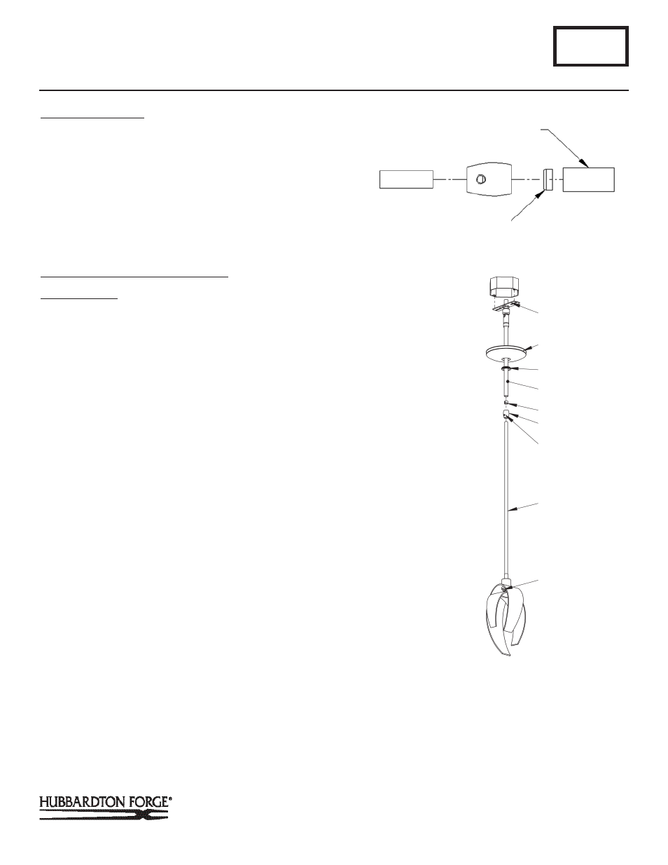
Complete Assembly & Install Fixture
(Figures 3 & 4)
Component Parts
A Fixture Pipe
C Crossbar
F Canopy
G Canopy Ring
H Canopy Pipe
I Plastic Sleeve
CAUTION: BE SURE POWER IS OFF AT THE MAIN BREAKER BOX
PRIOR TO INSTALLATION.
1. Place canopy (F) over canopy pipe (H), followed by canopy
ring (G). Make sure smaller diameter side of canopy ring is
oriented up toward the canopy.
2. Thread wires from the fixture pipe (A) through the canopy
pipe (H).
3. Unscrew the clutch (J) from the canopy pipe (H); slide it
across the wires and onto the fixture pipe (A). Follow this
with the plastic sleeve (I), oriented so the tapered end of the
sleeve nests in the clutch (J) (Figure 3).
4. Slide the canopy pipe (H) as far as necessary to give you
the total length of the fixture which you desire. Be careful
not to scratch the pipe surfaces and to pull excess wire
up through the canopy pipe (H). There must be a minimum
1-1/2" of inner pipe inside the outer pipe. Hand-tighten the
clutch to temporarily hold this adjustment. The clutch is not
securely fastened at this point; do not depend on it to hold
the fixture.
Important: To ensure full connection strength, be sure the tapered
end of the plastic clutch sleeve is oriented toward the clutch when
assembled and securely tighten set screw (Figure 3).
A299
Corona Adjustable Pendants 18650 & 18653
Page 2 of 3
M
F
G
H
(Figure 4)
TAPERED END OF
PLASTIC SLEEVE
LARGE DIAMETER PIPE
J Clutch
K Set Screw
L Socket
M Ground Screw
(Figure 3)
I
J
K
A
L
(Continued)