A303, Assembly & installation instructions – Hubbardton Forge 136505 User Manual
Page 3
H U B B A R D T O N F O R G E . C O M
hand-forged, vermont-made lighting and accessories
154 RT. 30 SOUTH
•
CASTLETON, VERMONT 05735
All designs and images ©1989-2013 Hubbardton Forge
®
. All rights reserved.
27146 Rev B
Assembly & Installation Instructions
If you need further assistance, or find that you are missing any parts, please contact the dealer from which you purchased this product.
We hope you enjoy your fixture!
* Hubbardton Forge will not be liable for injury or damage caused by improper installation, lamping or use of this fixture.
Complete Assembly & Install Fixture
(Figures 3, 4 & 5)
(Continued)
5. Carefully slide canopy ring (G) and canopy (F) down over
fixture pipe (K) until they rest on the fixture.
6. Using two machine screws (not provided), fasten the cross
bar (B) to the electric box.
Note: A new electric box comes with screws. When replacing a
fixture, retain the existing screws for use with the new fixture.
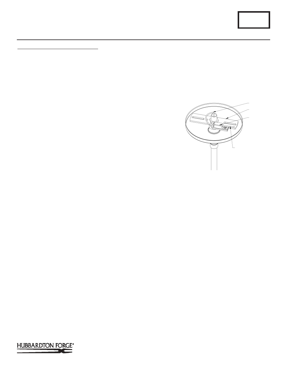
7. Thread support cable (A) through holes in crossbar (B) and
push into cable gripper (C) until cable is tight and has no
slack. Once support cable is at the correct height, excess
cable behind the gripper can be cut off (Figure 5, next page).
8. Using suitable wire connectors (not provided) connect
fixture wires to supply wires (white to white supply and
black to black supply). Run a pigtail lead from crossbar (B)
green ground screw to the junction box and connect
all ground wires (bare copper or green to bare copper or
green). Push wires back into outlet box.
CAUTION: MAKE SURE WIRE CONNECTORS ARE TWISTED ON
SECURELY, AND NO BARE WIRE IS EXPOSED.
9. Slide fixture canopy (F) against ceiling, and secure with
canopy ring (G).
10. Once the fixture is fastened to the ceiling, tighten the set
screw on the clutch (J) firmly with hex wrench provided.
Only after the set screw is tight should you install the glass.
A303
Corona Adjustable Pendants 136501 & 136505
Page 3 of 4
(Figure 5)
(Continued)
A
B
C
CUT OFF EXCESS
CABLE