A315, Assembly & installation instructions – Hubbardton Forge 138587 User Manual
Page 2
Assembly & Installation Instructions
A315
Aura LED Pendant 138587D
Page 2 of 3
Hand-Forged, Vermont-Made Lighting and Accessories
P.O. Box 827, 154 Route 30 South, Castleton, Vermont 05735
27760
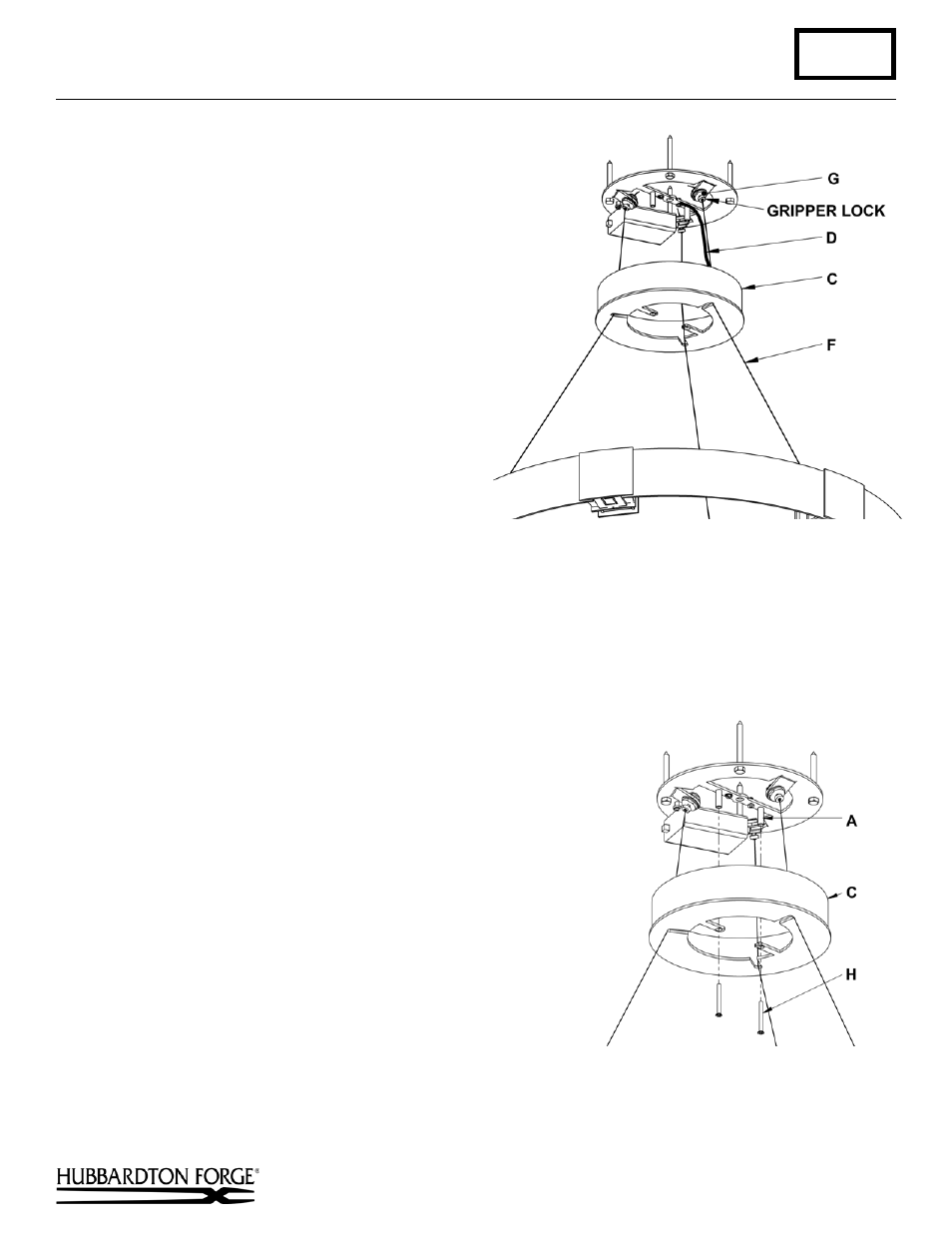
(Figure 3)
5. Raise fixture and push support cables (F) through
the canopy (C) and into the cable grippers (G)
until desired fixture height is accomplished and
level. Once desired height is accomplished and
product is level, tighten cable gripper locks.
(Figure 3).
6. Using heavy duty cable cutters, cut excess
supply/support cable (F) allowing enough left
(approx. 4”) to make connections. Locate support
cable (F) with a (+) label on the fixture and slip
the red isolation sleeve (provided) over the end.
Locate support cable (F) with a (-) label on the
fixture and slip the black isolation sleeve
(provided) over the end.
7.
Using suitable wire connectors (provided) connect
support cable (F) with red isolation sleeve to red
driver wire with (+) label attached. Connect
support cable (F) with black isolation sleeve to
black driver wire with (-) label attached. Driver
wires will be shipped with connector attached.
Caution: Make sure wire connectors are on
securely, and no bare wire is exposed.
Note: If using the supplied closed end connector,
please use the MR30A crimping tool.
8. Remove canopy support cable (D) by removing #8 screw (E) from one end and #8 nut from other end (discard
cable).
9. Raise the canopy (C) to the ceiling and attach to ceiling bracket (A) with two flat head screws (H) (Figure 4).
Note: Flat head screws (H) will need to be removed from ceiling bracket (A) prior to installation of the canopy (C).
The screws are shipped installed
.
10. Using suitable wire connectors (not provided) connect
fixture wires to supply (white to white or ribbed, black to black
or smooth). Connect all ground wires.
Caution: Make sure wire connectors are twisted on securely,
and no bare wire is exposed.
11. Slip canopy cover (J) onto canopy nipple (I) (Figure 5, next
page).
12.
Thread cap (K) on to canopy nipple (I). Tighten against canopy
cover (J) until snug
.
13. Refer to instructions following to install glass.
(continued)
(Figure 4)