Horner APG RCS RCS250 User Manual
Page 3
MAN0432-04
15 JAN 2010
PAGE 3
2.3
Ports, Connectors and Wiring
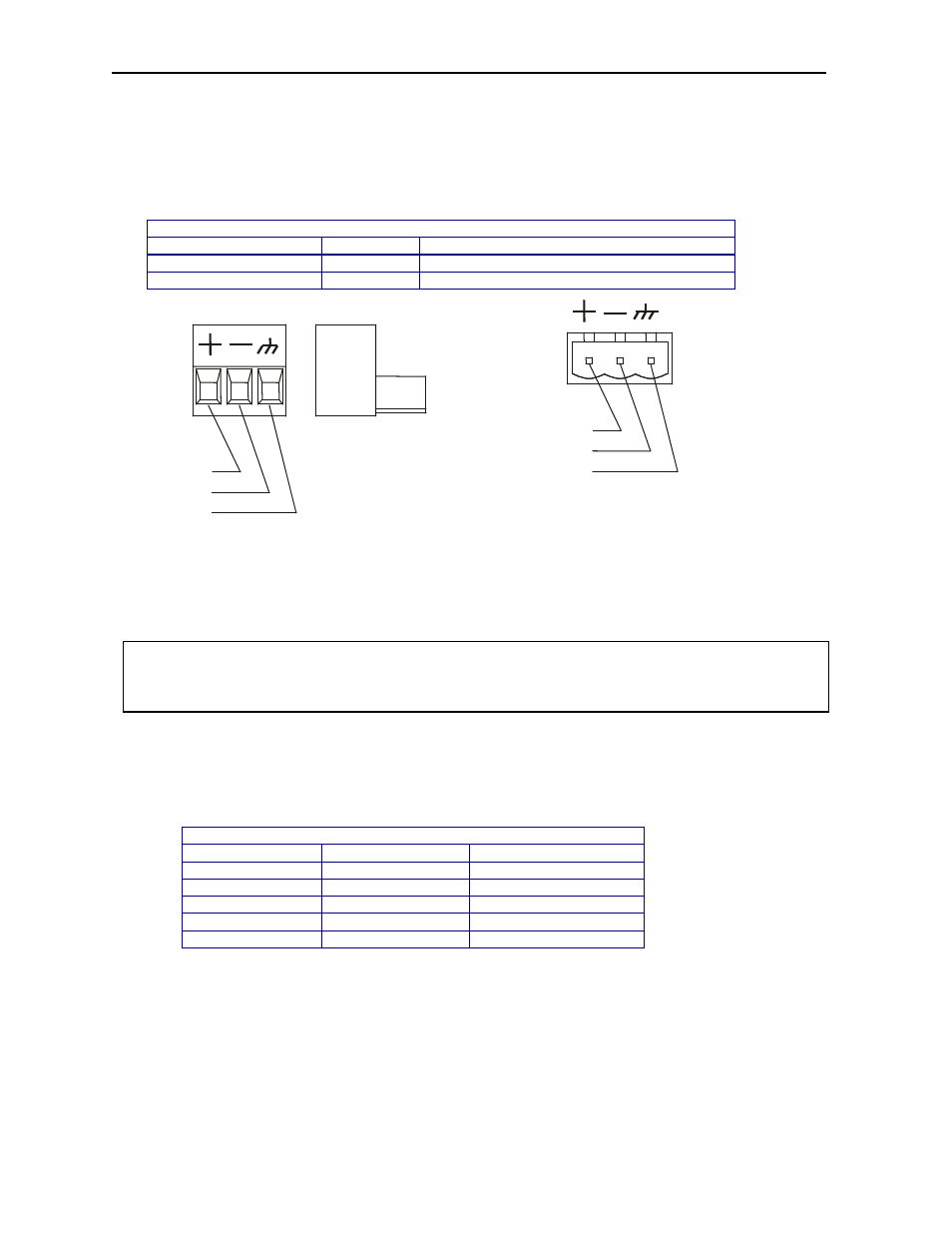
2.3.1
Primary Power Port
Table 2 – Primary Power Port Pins
Pin
Signal
Description
1
V+
Input power supply voltage
2
V-
Input power supply ground
Figure 3 - Power Connector (Primary Power Port) Figure 4 – As Viewed Looking at the RCS
Note: Power Supply Voltage Range is from 10-30 VDC.
2.3.2
CAN / DeviceNet Network Port and Wiring
a.
Network Connector
Table 3 – CAN Port Pins
Pin
Signal
Description
1
V-
Power -
2
CN_L
Signal -
3
SHLD
Shield
4
CN_H
Signal +
5
V+
Power +
Warning: To provide maximum noise immunity and to ensure minimum EMI radiation, the V-
signal (DC power return) need to be connected to earth ground at the power supply. The user must
ensure that the power supply selected is compatible with this method of grounding.
PIN 1
PIN 2
PIN 3
PIN 1
PIN 2
PIN 3