Horner APG RCX HE500OCX510 User Manual
Page 4
PAGE 4
10 MAR 2003
OCX510
Information is subject to change without notice. SmartStack is a trademark of Horner APG, LLC.
3
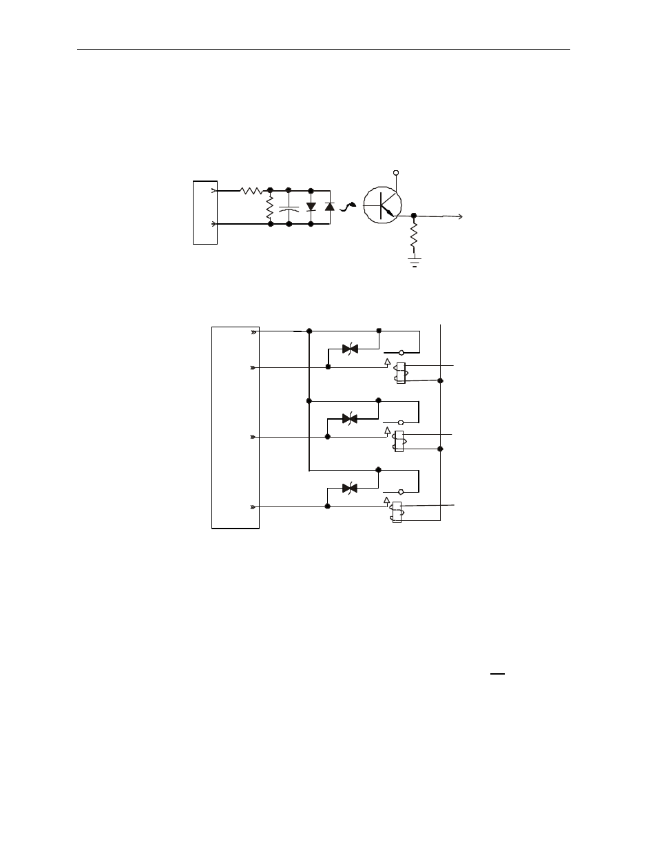
INTERNAL CIRCUIT SCHEMATIC
Specification for transient voltage suppressors (transorbs) used on output circuitry is 400VDC
bi-directional 400 watts.
Note: Electro-mechanical relays comply with IEC1131-2.
4
CONFIGURATION
Note: The status of the I/O can be monitored in Cscape Software.
Selecting the I/O Map tab provides information about the I/O registers. The I/O Map is not edited by the
user.
The Module Setup is used in applications where it is necessary to change the default states of the
outputs when the controller (e.g., Mini) enters idle/stop mode. The default turns the outputs OFF when
the controller enters idle/stop mode. By selecting the Module Setup tab, each output can be set to either
turn ON, turn OFF or to hold the last state. Generally, most applications use the default settings.
VCC
To
Controller
Input Connector
I1
C
Mini
Field
Side
+20-28V
+
+
-
+
-
Q1
Q2
Q3
C2
Output Connector
-
Field
Side
Mini