Horner APG XL6 OCS HEXT351C115 User Manual
Page 7
MAN0887-05-EN
Specifications / Installation
__________________________________________________________________________________________________________________________________________________________________
3/2/2010
Page 7 of 8 #1037
6
I/O Register Map
Registers
Description
%I1 to %I24
Digital Inputs
%I32
Output Fault
%I25 to %I31
Reserved
%Q1 to %Q16
Digital outputs
%Q17
Clear HSC1 accumulator to 0
%Q18
Totalizer: Clear HSC2
Quadrature 1-2: Accumulator 1 Reset to
max – 1
%Q19
Clear HSC3 Accumulator to 0
%Q20
Totalizer: Clear HSC4
Quadrature 3-4: Accumulator 3 Reset to
max – 1
%Q21 to %Q32
Reserved
%AI1 to %AI4
Analog inputs
%AI5, %AI6
HSC1 Accumulator
%AI7, %AI8
HSC2 Accumulator
%AI9, %AI10
HSC3 Accumulator
%AI11, %AI12
HSC4 Accumulator
%AQ1, %AQ2
PWM1 Duty Cycle
%AQ3, %AQ4
PWM2 Duty Cycle
%AQ5, %AQ6
PWM Prescale
%AQ7, %AQ8
PWM Period
%AQ9 to %AQ14
Analog outputs
Note: Not all XL6 units contain the I/O listed in this table.
Registers
PWM
HSC
Stepper
%AQ1
Start Frequency
%AQ2
PWM1 Duty Cycle
(32 bit)
HSC1
Preset
Value
Run Frequency
%AQ3
%AQ4
PWM2 Duty Cycle
(32 bit)
HSC2
Preset
Value
Accel Count (32
bit)
%AQ5
%AQ6
PWM Prescale
(32 bit)
Run Count (32
bit)
%AQ7
%AQ8
PWM Period
(32 bit)
Decel Count (32
bit)
%Q1
Run
%I30
Ready/Done
%I31
Error
7
Digital Filtering for Analog Inputs
The digital filter is updated once per conversion. It is an “IIR” running average filter that emulates a simple
RC filter. The equivalent time constant is determined by the Filter Constant and the sum of the conversion
times for the two channels. The Filter Constant determines the weight given to the most recent
conversion. The following table lists the equivalent time constant for the three possible total conversion
times, which are dependent upon the two input mode selections. This filter delay is in addition to the PLC
scan delay.
Equivalent RC Time Constant in Seconds
(Nominal time to reach 63% of final value.)
Total Conversion Time in Seconds
Filter Constant
0.03
0.09
0.13
0*
0.03*
0.09*
0.13*
1
0.07
0.18
0.27
2
0.13
0.35
0.53
3
0.27
0.71
1.07
4
0.53
1.41
2.13
5
1.07
2.83
4.27
6
2.14
5.65
8.54
7
4.28
11.30
17.08
* No filter delay, reading is unfiltered conversion value
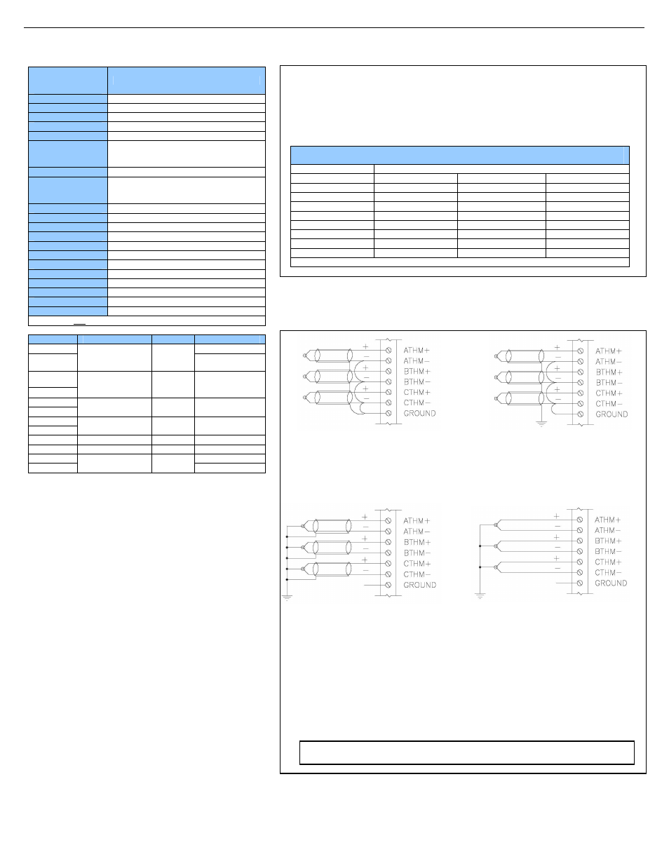
8
Thermocouple Grounding Schemes
Ungrounded Thermocouples
Alternate Shield Connection for
Ungrounded Thermocouples.
Ungrounded Thermocouples
Preferred Shield Connection for
Ungrounded Thermocouples.
Grounded Thermocouples
Field Ground Potential Less Than
Seven Volts AC
Typical Shield Connection for
Grounded Thermocouples
Grounded Thermocouples
Field Ground Potential Less Than
Seven Volts AC
Shields Connected at One End Only
May be Used to Reduce Noise
Grounded Thermocouples May Use
the Ungrounded Thermocouple Shield
Connections if the Shield is not
Grounded at the Field End
Note: The examples for thermocouple grounding schemes above are generic illustrations. The
XL6 model XL105 has two thermocouple inputs.