Horner APG XL6 OCS HEXT351C115 User Manual
Page 5
MAN0887-05-EN
Specifications / Installation
__________________________________________________________________________________________________________________________________________________________________
3/2/2010
Page 5 of 8 #1037
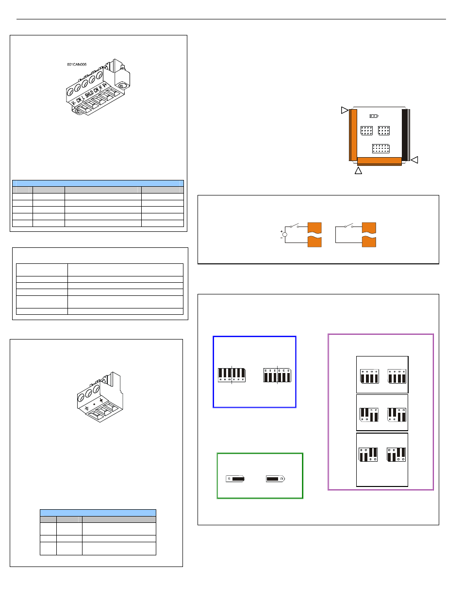
4.3
CAN Network Port and Wiring
NET1 Port Pin Assignments
Pin
Signal
Signal Description
Direction
1
V-
CAN Ground
−
2
CN_L
CAN Data Low
In/Out
3
SHLD
Shield Ground
−
4
CN_H
CAN Data High
In/Out
5
NC
No Connect
−
4.4
Ethernet Port
Speeds
10 BaseT Ethernet (10-Mbps)
100 BaseTx Fast Ethernet (100-Mbps)
Modes
Half or Full Duplex
Auto-Negotiation
Both 10/100-Mbps and Half/Full Duplex
Connector Type
Shielded RJ-45
Cable Type
(Recommended)
CAT5 (or better) UTP
Port
Auto MDI/MDI-X
4.5
Power Port and Wiring
Primary Power Port Pins
Pin
Signal
Description
1
Ground
Frame Ground
2
V-
Input Power Supply Ground
3
V+
Input Power Supply Voltage
5
Wiring and Jumpers
•
Wire according to the type of inputs / outputs used and select the appropriate jumper option.
•
Use Copper Conductors in Field Wiring Only, 60/75° C
5.1
I/O Jumpers Settings (JP1 – JP4)
Note: The Cscape Module Setup configuration must match the selected I/O (JP) jumper settings.
I1
0V
001XLE036
12-24VDC
I1
0V
Positive Logic In Negative Logic In
Positive Logic vs. Negative Logic Wiring
The XL6 can be wired for Positive Logic inputs or
Negative Logic inputs.
Wiring Specifications
For I/O wiring (discrete), use the
following wire type or equivalent:
Belden 9918, 18 AWG (0.8 mm
2
)
or larger.
For shielded Analog I/O wiring,
use the following wire type or
equivalent: Belden 8441, 18
AWG (0.8 mm
2
) or larger.
For CAN wiring, use the
following wire type or equivalent:
Belden 3084, 24 AWG (0.2 mm
2
)
or larger.
Analog In Settings
AI1 AI2
JP2
JP3
RTD (PT100)
T1
T2
JP2
JP3
T/C/100mV
T1
T2
Note: When using JP4 (output) or JP2 / JP3
(inputs), each channel can be independently
configured. For example, JP2 can be configured
for 10 V and JP3 can be configured as an RTD.
JP2
JP3
10V/20mA
MA1/V1
MA2/V2
Default
J1
J2
J3
JP2
JP1
JP3
JP4
001XLE030
Location of I/O jumpers (JP)
and wiring connectors
(J1 – J3).
CAN Connector
Use the CAN Connector when
using CsCAN network.
Torque rating 4.5 – 7 Lb-In
(0.50 – 0.78 N-m)
CURRENT
(20mA)
VOLTAGE
(10V)
JP4
ANALOG OUTPUT SETTING
VOLTAGE OR CURRENT
AQ2
AQ1
AQ2
AQ1
Default
Negative Logic
Positive Logic
JP1 Digital DC Inputs
Default
JP2 and JP3
Power Connector
Power Up:
Connect to Earth Ground.
Apply 10 - 30 VDC.
Screen lights up.
Torque rating 4.5 – 7 Lb-In
(0.50 – 0.78 N-m)