Horner APG XL6 OCS HE-XL1E14 User Manual
Page 6
MAN0902-01-EN
Specifications / Installation
__________________________________________________________________________________________________________________________________________________________________
3/26/2009 Page 6 of 7 ECN # 956
6.2
Thermistor Linearization
Thermistors are measured using a half-bridge circuit that exhibits variable
resolution and the associated increased measurement range.
Temperature, degrees C
Resolution, degrees C
-55
1.05
-35
0.36
-15
0.17
5
0.11
25
0.1
45
0.13
65
0.22
85
0.30
105
0.55
125
0.85
145
1.35
Best resolution is at 25°C, 77°F. With a constant 0.1°C resolution circuit,
the measurement range would only extend from –26°C to +76°C.
Linearization must be performed by the user in the ladder application
code, using 26 internal %R registers per channel. The example below
uses %R1-26 to linearize one channel - %AI1. Linearization consists of
the following example steps.
1)
Load the desired linearization coefficients into a table on First
Scan using a Move Constant Data block.
Registers (Real)
Degrees C
Degrees F
R0011
-1.94454e-028
-3.50017e-028
R0013
2.40268e-023
4.32483e-023
R0015
-1.24101e-018
-2.23381e-018
R0017
3.46655e-014
6.23979e-014
R0019
-5.69403e-010
-1.02493e-009
R0021
5.62368e-006
1.01226e-005
R0023
-0.0353121
-0.0635617
R0025
163.878
326.981
2)
Load %AI0001 into %R0001 as a Real.
3)
Perform the Real Math Expression
4)
%R3 = (((%R11*%R1+%R13)*%R1+%R15)*%R1+%R17)
5)
Perform the Real Math Expression %R5 =
(((%R3*%R1+%R19)*%R1+%R21)*%R1+%R23)*%R1+%R25
6)
Load %R0005 result into another register such as %R0007 to
save the temperature value.
7)
Steps 2 though 5 can be on a single rung.
The expression rung may be copied, substituting %AI0002 and %R00011
for %AI0001 and %R0007, and used to linearize the second channel.
Contact Horner APG Technical Support for an example file containing the
above program.
6.3
Thermistor Types
The HE-XL102-14/HE-XL1E2-14 with the given example ladder code
supports Kele Engineering Precon Type III, 10 K
Ω
thermistors. It also
directly supports the following 10 K
Ω
(Beta=3574) thermistors from Yellow
Springs Instruments (YSI).
44006 46006
44106 46031
44406 46041
44031 44907
45006 44908
7
Derating
8
I/O Register Map
9
Safety
Registers
Description
%I1 to %I24
Digital Inputs
%I32
Output Fault
%I25 to %I31
Reserved
%Q1 to %Q16
Digital outputs
%Q17
Clear HSC1 accumulator to 0
%Q18
Totalizer: Clear HSC2
Quadrature 1-2: Accumulator 1 Reset to max – 1
%Q19
Clear HSC3 Accumulator to 0
%Q20
Totalizer: Clear HSC4
Quadrature 3-4: Accumulator 3 Reset to max – 1
%Q21 to %Q32
Reserved
%AI1 to %AI4
Analog inputs
%AI5, %AI6
HSC1 Accumulator
%AI7, %AI8
HSC2 Accumulator
%AI9, %AI10
HSC3 Accumulator
%AI11, %AI12
HSC4 Accumulator
%AQ1, %AQ2
PWM1 Duty Cycle
%AQ3, %AQ4
PWM2 Duty Cycle
%AQ5, %AQ6
PWM Prescale
%AQ7, %AQ8
PWM Period
%AQ9 to %AQ14
Analog outputs
Note: Not all XL6 units contain the I/O listed in this table.
This equipment is suitable for use in Class I, Division 2, Groups A, B, C and D or Non-hazardous
locations only
WARNING – EXPLOSION HAZARD – Do not disconnect equipment unless power has been
switched off or the area is known to be non-hazardous.
AVERTISSEMENT - RISQUE D'EXPLOSION - AVANT DE DECONNECTOR L'EQUIPMENT,
COUPER LE COURANT OU S'ASSURER QUE L'EMPLACEMENT EST DESIGNE NON
DANGEREUX.
WARNING: To avoid the risk of electric shock or burns, always connect the safety (or earth) ground
before making any other connections.
WARNING: To reduce the risk of fire, electrical shock, or physical injury it is strongly recommended
to fuse the voltage measurement inputs. Be sure to locate fuses as close to
the source as possible.
WARNING: Replace fuse with the same type and rating to provide protection against risk of fire and
shock hazards.
WARNING: In the event of repeated failure, do not replace the fuse again as a repeated failure
indicates a defective condition that will not clear by replacing the fuse.
WARNING – EXPLOSION HAZARD – Substitution of components may impair suitability for Class I,
Division 2.
AVERTISSEMENT - RISQUE D'EXPLOSION - LA SUBSTITUTION DE COMPOSANTS PEUT
RENDRE CE MATERIAL INACCEPTABLE POUR LES EMPLACEMENTS DE CLASSE 1,
DIVISION 2.
WARNING - The USB parts are for operational maintenance only. Do not leave permanently
connected unless area is known to be non-hazardous.
WARNING – EXPLOSION HAZARD - BATTERIES MUST ONLY BE CHANGED IN AN AREA
KNOWN TO BE NON-HAZARDOUS
AVERTISSEMENT - RISQUE D'EXPLOSION - AFIN D'EVITER TOUT RISQUE D'EXPLOSION,
S'ASSURER QUE L'EMPLACEMENT EST DESIGNE NON DANGEREUX AVANT DE CHANGER
LA BATTERIE.
WARNING - Battery May Explode If Mistreated. Do Not Recharge, Disassemble or Dispose Of In
Fire.
WARNING: Only qualified electrical personnel familiar with the construction and operation of this
equipment and the hazards involved should install, adjust, operate, or service this equipment. Read
and understand this manual and other applicable manuals in their entirety before proceeding.
Failure to observe this precaution could result in severe bodily injury or loss of life.
Warning: Consult
user documentation.
Warning: Electrical
Shock Hazard.
When found on the product, the following symbols specify:
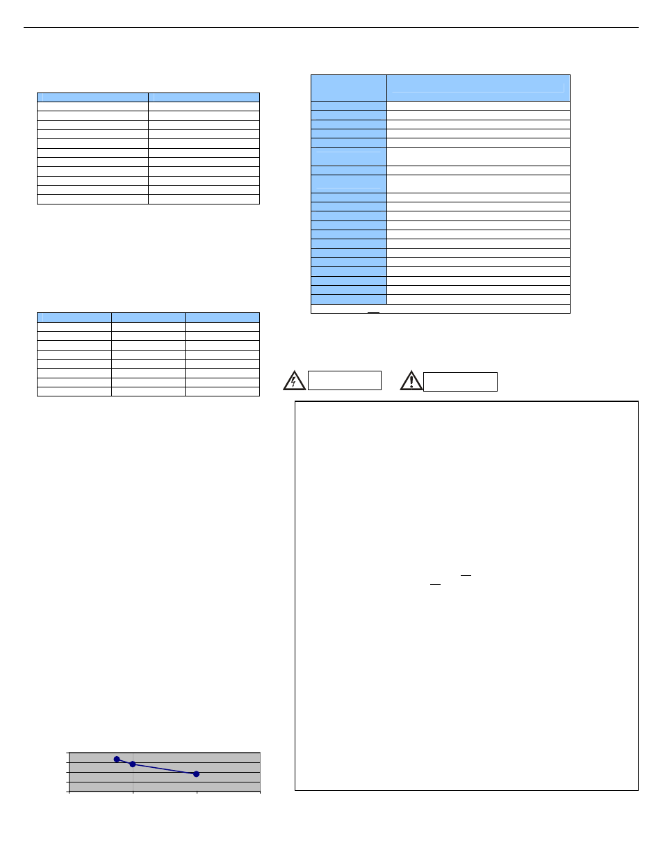
Relay Life Expectancy
0
10
20
30
40
1
2
3
4
Contact Current (A)
O
p
e
ra
ti
o
n
(x
1
0
4
)