Horner APG XL6 OCS HE-XL1E14 User Manual
Page 4
MAN0902-01-EN
Specifications / Installation
__________________________________________________________________________________________________________________________________________________________________
3/26/2009 Page 4 of 7 ECN # 956
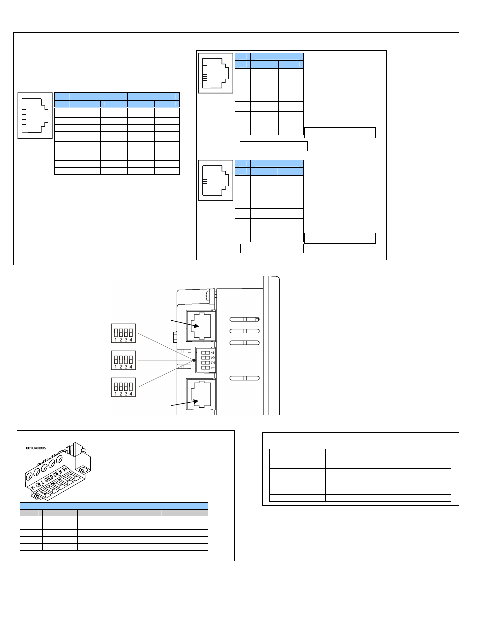
4.2
External DIP Switch Settings
MJ2 Pinouts in Half and Full Duplex Modes
NET1 Port Pin Assignments
Pin
Signal
Signal Description
Direction
1
V-
CAN Ground
−
2
CN_L
CAN Data Low
In/Out
3
SHLD
Shield Ground
−
4
CN_H
CAN Data High
In/Out
5
NC
No Connect
−
Speeds
10 BaseT Ethernet (10-Mbps)
100 BaseTx Fast Ethernet (100-Mbps)
Modes
Half or Full Duplex
Auto-Negotiation
Both 10/100-Mbps and Half/Full Duplex
Connector Type
Shielded RJ-45
Cable Type
(Recommended)
CAT5 (or better) UTP
Port
Auto MDI/MDI-X
4.1
Serial Communications:
MJ1: (RS-232 / RS-485) Use for Cscape programming
and Application-Defined Communications.
MJ2: (RS-232 / RS-485) Use for Application-Defined
Communications.
As seen when looking at the side of the XL6 unit :
The DIP Switches are used for
termination of the RS-485 ports. The
XL6 is shipped un-terminated.
To terminate, select one of the DIP
Switches and configure it based upon
the option that is desired.
Pin
MJ1 Pins
MJ2 Pins
Signal
Direction
Signal
Direction
8
TXD
OUT
TXD
OUT
7
RXD
IN
RXD
IN
6
0 V
Ground
0 V
Ground
5*
+5 60mA
OUT
+5 60mA
OUT
4
RTS
OUT
TX-
OUT
3
CTS
IN
TX+
OUT
2
RX- / TX-
IN / OUT
RX-
IN
1
RX+ / TX+
IN / OUT
RX+
IN
1
8
SW1 -
ON enables MJ2 RS485 port termination (121 Ohms).
OFF disables MJ2 RS485 port termination.
SW2 & SW3 - ON places MJ2 RS485 port in half-duplex mode.
OFF places MJ2 RS485 port in full-duplex mode.
SW4 -
ON enables MJ1 RS485 port termination (121 Ohms).
OFF disables MJ1 RS485 port termination.
MJ1
MJ2
On
Off
On
Off
On
Off
CAN Connector
Use the CAN Connector when using CsCAN network.
Torque rating 4.5 – 7 Lb-In
(0.50 – 0.78 N-m)
4.3
CAN Network Port and Wiring
4.4
Ethernet Port
* +5V 60mA Max
MJ2 Half Duplex Mode
Pin
MJ2 Pins
Signal
Direction
8
TXD
OUT
7
RXD
IN
6
0 V
Ground
5*
+5 60mA
OUT
4
TX-
OUT
3
TX+
OUT
2
TX-/RX-
IN/OUT
1
TX+/RX+
IN/OUT
1
8
Pin
MJ2 Pins
Signal
Direction
8
TXD
OUT
7
RXD
IN
6
0 V
Ground
5*
+5 60mA
OUT
4
TX-
OUT
3
TX+
OUT
2
RX-
IN
1
RX+
IN
1
0
-
* +5V 60mA Max
MJ2 Full Duplex Mode