Model 3 & model 4 i/o – Horner APG XL4 OCS User Manual
Page 5
MAN0963-07EN
Specifications / Installation
August 23, 2012
Specifications / Installation
Page 5 of 6
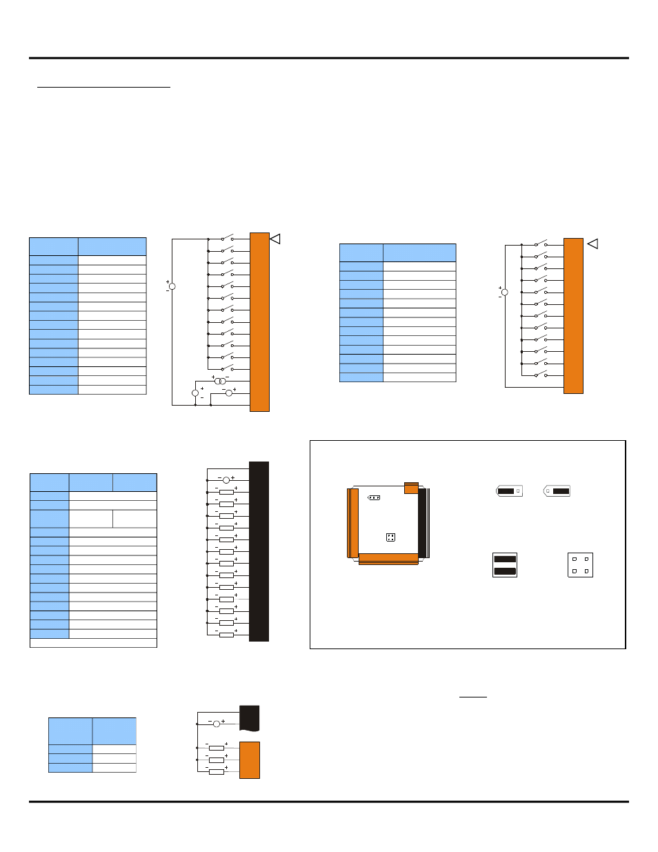
Model 3 & Model 4 I/O
The XL4 model 3 (HE-XC1E3) features 12 DC Inputs, 12 DC outputs, and 2 Analog Inputs. The XL4 model 4 (HE-XC1E4)
increases the I/O count up to 24 DC Inputs, and 16 DC Outputs and 2 Analog Inputs. The DC Inputs are 12/24Vdc
compatible, and can be jumpered for Positive Logic (sinking), or Negative Logic (sourcing). Four of the inputs (H1-H4) can
be used for high-speed functions up to 500kHz. The 12-bit Analog Inputs can be jumpered for voltage (0-10V) or current
(4-20mA) on a channel by channel basis. The 12/24VDC Outputs feature Electronic Short Circuit protection, and support
currents up to 0.5A per point, and 4A total. Two of the DC Outputs can be used for high speed functions (PWM or PTO).
The output frequency is limited by the switching capability of the output drivers (about 10kHz), although an optional
accessory (HE-XHSQ) can be added to provide parallel output drivers supporting frequencies up to 200kHz.
J1
(Orange)
Model 3 & 4
Signal Name
I1
IN1
I2
IN2
I3
IN3
I4
IN4
I5
IN5
I6
IN6
I7
IN7
I8
IN8
H1
HSC1 / IN9
H2
HSC2 / IN10
H3
HSC3 / IN11
H4
HSC4 / IN12
A1
Analog IN1
A2
Analog IN2
0V
Common
J3
(Orange)
Model 4 only
Signal Name
I13
IN13
I14
IN14
I15
IN15
I16
IN16
I17
IN17
I18
IN18
I19
IN19
I20
IN20
I21
IN21
I22
IN22
I23
IN23
I24
IN24
0V
Common
J3 Orange
Positive Logic
Digital In
J2
(Black)
Model 3
Name
Model 4
Name
0V
Common
V+
V+ *
NC
No
Connect
OUT13
Q12
OUT12
Q11
OUT11
Q10
OUT10
Q9
OUT9
Q8
OUT8
Q7
OUT7
Q6
OUT6
Q5
OUT5
Q4
OUT4
Q3
OUT3
Q2
OUT2 / PWM2
Q1
OUT1 / PWM1
*V+ Supply for Sourcing Outputs
J4 Orange
Positive Logic
Digital Out
Q14
Q15
V+
0V
LOAD
LOAD
10 - 30VDC
Q16
LOAD
J2
J4
J4
(Orange)
Model 4
Name
Q16
OUT16
Q15
OUT15
Q14
OUT14
Location of I/O jumpers
(JP1 & JP3) and
wiring connectors
(J1, J2, J3 & J4) with back
cover removed.
Negative Logic
Positive Logic
JP1 Digital DC Inputs
Default
Jumper Setting Details
Note: The Cscape Module Setup configuration
must match the selected I/O (JP) jumper
settings.
Note: When using JP3 (A1-A2), each channel
can be independently configured.
JP3 Analog Inputs
I13
I14
I15
I16
I22
I23
I24
0V
I17
I18
I19
I20
I21
001XLE047
12-24VDC
Q1
Q2
Q3
Q4
Q9
Q10
Q11
Q12
Q5
Q6
Q7
Q8
V+
0V
LOAD
LOAD
LOAD
LOAD
LOAD
LOAD
LOAD
LOAD
LOAD
LOAD
LOAD
LOAD
10 - 30VDC
Q13
001XLE024
LOAD
J2 Black
Positive Logic
Digital Out
J1
J2
J3
JP3
JP1
001XLE005-R1
J4
20mA
10VDC
JP3
CURRENT OR VOLTAGE INPUTS
001XLE043-R1
A1
A2
A1
A2
1
1
2
2
3
3
4
4
I1
I2
I3
I4
0V
I5
I6
I7
I8
H1
001XLE046
12-24VDC
LOOP
PWR
20mA
0-10VDC
A1
A2
H2
H3
H4
J1 Orange
Positive Logic
Digital & Analog In
Note:
Model 3 uses
J1 & and J2 only.
Model 4 uses
J1, J2, J3 & J4.