5 safety, 6 technical support – Horner APG XL4 OCS User Manual
Page 3
MAN0963-07EN
Specifications / Installation
August 23, 2012
Specifications / Installation
Page 3 of 6
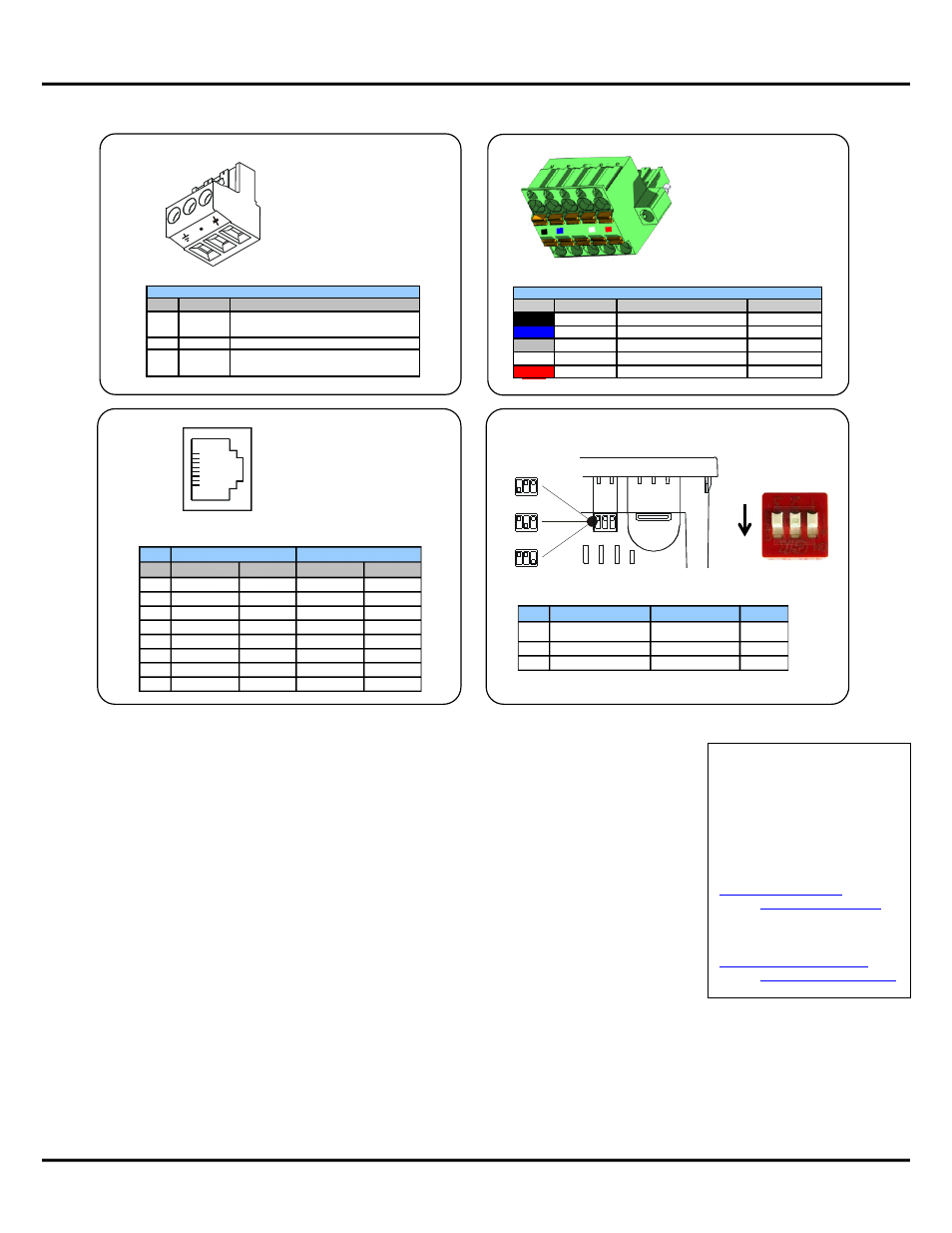
DC Input / Frame
Torque rating
4.5 – 7 Lb-In
(0.50 – 0.78 N-m)
DC- is internally connected to
I/O V-, but is isolated from
CAN V-
A Class 2 power supply must
be used.
!
Primary Power Port Pins
Pin
Signal
Description
1
Ground
Frame Ground
2
DC-
Input Power Supply Ground
3
DC+
Input Power Supply Voltage
MJ1/2 Serial Ports
MJ1: RS-232 w/Full
Handshaking
MJ2: RS-485 Half-Duplex
Two Serial Ports on One Modular Jack
(8posn)
!
1"
!
8"
!
Pin
MJ1 Pins
MJ2 Pins
Signal
Direction
Signal
Direction
8
TXD
OUT
-
-
7
RXD
IN
-
-
6
0 V
Ground
0 V
Ground
5
+5V@60mA
OUT
+5V@60mA
OUT
4
RTS
OUT
-
-
3
CTS
IN
-
-
2
-
-
RX- / TX-
IN / OUT
1
-
-
RX+ / TX+
IN / OUT
1 2
3
ON
DIP Switches
Pin
Name
Function
Default
1
RS-485 Termination
ON = Terminated
OFF
2
Spare
Always Off
OFF
3
Factory Use
Always Off
OFF
5 Safety
WARNING: Only qualified electrical personnel familiar with the construction and operation of this equipment and the hazards
involved should install, adjust, operate, or service this equipment. Read and understand this manual and other applicable manuals
in their entirety before proceeding. Failure to observe this precaution could result in severe bodily injury or loss of life.
WARNING: To avoid the risk of electric shock or burns, always connect the earth ground before making any other connections.
WARNING: To reduce the risk of fire, electrical shock, or physical injury it is strongly recommended to fuse all Power Sources
connected to the OCS. Be sure to locate fuses as close to the source as possible.
WARNING: Replace fuse with the same type and rating to provide protection against risk of fire and shock hazards.
WARNING: In the event of repeated failure, do not replace the fuse again as a repeated failure indicates a defective condition that
will not clear by replacing the fuse.
WARNING: Battery may explode if Mistreated. Do Not Recharge, Disassemble or Dispose Of in Fire.
WARNING: EXPLOSION HAZARD – BATTERIES MUST ONLY BE CHANGED IN AN AREA KNOWN TO BE NON-HAZARDOUS
Power input and output (I/O) wiring must be in accordance with Class I, Division 2 wiring methods of the National Electric Code,
NFPA 70 for installations in the U.S., or as specified in Section 18-1J2 of the Canadian Electrical Code for installations within
Canada and in accordance with the authority having jurisdiction.
This equipment is suitable for use in Class I, Division 2, Groups A, B, C, and D or Non-hazardous locations only.
WARNING: EXPLOSION HAZARD – Do not disconnect equipment unless power has been switched off or the area is known to be
non-hazardous.
WARNING: EXPLOSION HAZARD – Substitution of components may impair suitability for Class 1, Division 2.
Digital outputs shall be supplied from the same source as the Operator Control Station.
Jumpers on connector JP1 and others shall not be removed or replaced while the circuit is live unless the area is known to be free
of ignitable concentrations of flammable gasses or vapors.
CAN
Locking Spring-Clamp,
Two-terminators Per Conductor
Torque rating 4.5 Lb-In
(0.50 N-m)
SHLD and V+ pins are not
internally connected to XL4
CAN1 Port Pin Assignments
Pin
Signal
Signal Description
Direction
1
V-
CAN Ground - Black
−
2
CN_L
CAN Data Low - Blue
In/Out
3
SHLD
Shield Ground - None
−
4
CN_H
CAN Data High - White
In/Out
5
V+ (NC)
No Connect - Red
−
!
001XLE037-R1
6 Technical Support
For assistance and manual
updates, contact Technical
Support at the following
locations:
North America
(317) 916-4274
877-665-5666
http://www.heapg.com
e-mail:
Europe
(+) 353-21-4321-266
http://www.horner-apg.com
e-mail: