2 user input wiring, 3 setpoint (output) wiring, 4 input signal wiring – Red Lion PAXLA User Manual
Page 4: 1 power wiring, User 8 user com 9, Comm + exc 4 3, 12 l1 l2
4
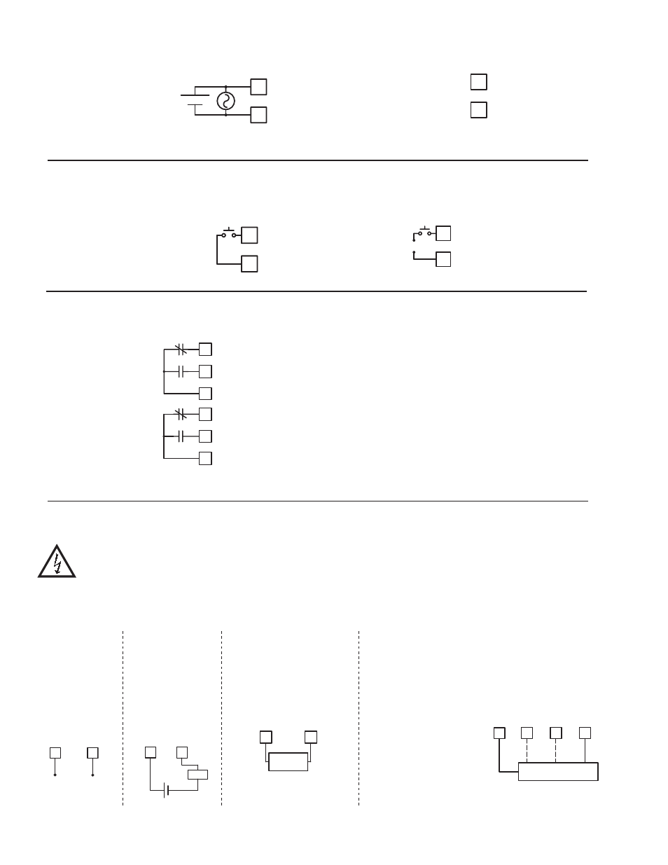
3.2 USER INPUT WIRING
CAUTION: Analog common is NOT isolated from user input common. In order to preserve the safety of the meter
application, the Analog and DC power common must be suitably isolated from hazardous live earth referenced voltage; or
input common must be at protective earth ground potential. If not, hazardous voltage may be present at the User Input and
Input Common terminals. Appropriate considerations must then be given to the potential of the input common with respect
to earth ground. Always connect the analog signal common to terminal 7.
Terminal 8: User Input
Terminal 9: User Comm
3.3 SETPOINT (OUTPUT) WIRING
Terminal 10: NC 1
Terminal 11: NO 1
Terminal 12: Relay 1 Common
Terminal 13: NC 2
Terminal 14: NO 2
Terminal 15: Relay 2 Common
USER
8
USER COM
9
USER
USER COMM
9
8
+
-
10 N.C. 1
COMM 1
12
11 N.O. 1
13
14
15
N.C. 2
N.O. 2
COMM 2
Sinking Logic
Sourcing Logic
Current Signal
(self powered)
Terminal 6: +ADC
Terminal 7: -ADC
Voltage Signal
(self powered)
Terminal 5: +VDC
Terminal 7: -VDC
Current Signal (2 wire
requiring excitation)
Terminal 3: +EXC
Terminal 6: +ADC
5
7
+
-
200 VDC MAX.
VO
LT
ANALOG COMM
3.4 INPUT SIGNAL WIRING
Current Signal (3 wire
requiring excitation)
Terminal 6: +ADC (signal)
Terminal 7: -ADC (common)
Terminal 3: +EXC
Voltage Signal (3 wire
requiring excitation)
Terminal 5: +VDC (signal)
Terminal 7: -VDC (common)
Terminal 3: +EXC
Load
200 MA DC MAX.
ANALOG COMM
6
-
7
CURREN
T
+
3 WIRE TRANSMITTER
VO
LT
5
Iout
Vout
6
7
CURREN
T
ANALOG COMM
COMM
+ EXC
.
3
TRANSMITTER
-
CURREN
T
3
2 WIRE
6
+ EXC
.
+
3.1 POWER WIRING
COMM
+ EXC
4
3
DC Out Power
Terminal 3: + 24 VDC OUT
Terminal 4: Common
Power
Terminal 1: VAC/DC +
Terminal 2: VAC/DC -
1
2
L1
L2
+
-