1 module 1 - i, Nput, Etup – Red Lion PAXLCR User Manual
Page 6: Arameters
COUNTER A DECIMAL POSITION
This selects the decimal point position for Counter A. The selection will also
affect Counter A scale factor calculations.
COUNTER A SCALE FACTOR
The number of input counts is multiplied by the scale factor to obtain the
desired process value. A scale factor of 1.0000 will result in the display of the
actual number of input counts. (Details on scaling calculations are explained at
the end of this section.)*
to
COUNTER B DECIMAL POSITION
This selects the decimal point position for Counter B. The selection will also
affect Counter B scale factor calculations.
COUNTER A COUNT LOAD VALUE
Counter A resets to this value if Reset to Count Load action is selected. To
enter a negative Count Load value, increment digit 6 to display a “-” sign.*
to
PAR
1-INP
Pro
Dual Count or Batch
Only
Counter B
Scale Factor
Counter A
Reset Action
A-rSt
A-Scf
INP Ab
A-dPt
Counter A
Decimal Point
Count
Mode
Counter B
Decimal Point
Counter A
Scale Factor
Dual Count or
Batch Only
Counter B
Batch Count
Enable
b-bAt
Cnt Ld
A-dir
USrINP
Counter A
Count Direction
Counter Reset
at Power-up
r P-UP
User Input
Function
User Input
Assignment
Counter A
Count Load
Value
b-ScF
b-dPt
USrASN
5.1 MODULE 1 - I
NPUT
S
ETUP
P
ARAMETERS
(
)
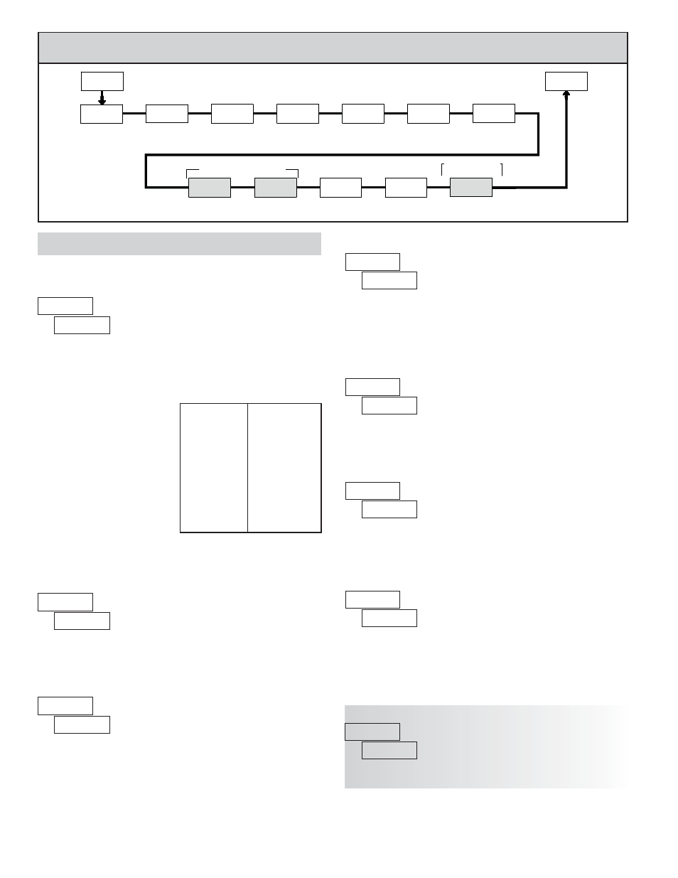
PARAMETER MENU
COUNT MODE
Select the count mode that corresponds with your application. The input
actions are shown in the boxes below. For simple counting applications, it is
recommended to use Count with Direction for the count mode. Simply leave the
direction input unconnected.
Shaded area selections only apply when Counter B is enabled (Dual Count
mode or batch counter).
Counter A Subtract
Counter A Add
Counter A Add
Counter A Add
Quad A
Count A
Quad A
Count A
Quad A
Count A
Counter B Add
Counter A Add
Counter A Add
Rate only
Counter A Direction
Counter A
INPUT B ACTION
INPUT A ACTION
2 Input Add/Subtract
2 Input Add/Add
Quadrature x4
Quadrature x2
Quadrature x1
Dual Counter
Rate/Counter
Count with Direction
DISPLAY
MODE
Note: The Rate indicator signal is derived from Input A in all count modes.
6
COUNTER A RESET ACTION
When Counter A is reset, it returns to Zero or Counter A Count Load value.
This reset action applies to all Counter A resets, except a Setpoint generated
Counter Auto Reset programmed in Module 4.
COUNTER B BATCH COUNT ENABLE
The Counter B Batch Count function internally counts the number of output
activations of the selected setpoint(s). The count source for the batch counter
can be SP1, SP2 or both. Batch counting is available in all count modes except
Dual Counter, which uses an external input signal for Counter B.
COUNTER A COUNT DIRECTION
Reverse (
) switches the normal Counter A count direction shown in the
Count Mode parameter chart.
*For value entry instructions, refer to selection/value entry in the Programming
The Meter section.