4 module 4 - s, Etpoint, Utput – Red Lion PAXLCR User Manual
Page 10: Arameters, Parameter menu
10
5.4 MODULE 4 - S
ETPOINT
O
UTPUT
P
ARAMETERS
(
)
PAR
4-SPt
Pro
StbY-n
Setpoint
Standby
Operation
ACt-n
Setpoint Output
Power-up
State
P-UP-n
tYPE-n
Setpoint
Boundary
Type
Enb-n
Setpoint
Enable
Setpoint
Select
SP SEL
Setpoint
Assignment
ASN-n
SP2 Output
Off at SP1
Output
OUt-n
Setpoint
Output Logic
AUtO-n
Counter
Auto Reset
SP1 Output
Off at SP2
Output
Setpoint
Output
Action
Setpoint
Output
Time-out
tOUt-n
SPt-n
Setpoint
Value
Setpoint
Output Reset
with Manual
Reset
rSt-n
Setpoint
Annunciator
LIt-n
SP1 Only
SP2 Only
OFF1-2
OFF2-1
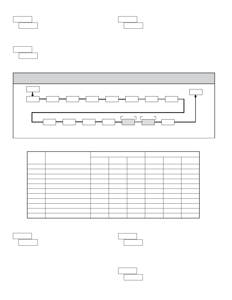
PARAMETER MENU
Select the Setpoint Output to be programmed, starting with Setpoint 1. The
“
” in the following parameters reflects the chosen Setpoint number. After the
selected setpoint is completely programmed, the display returns to
.
Repeat steps for Setpoint 2 if both Setpoints are being used. Select
to exit the
Setpoint programming module.
SETPOINT SELECT
Select
to enable the chosen setpoint and access the setup parameters. If
is selected, the unit returns to
and the setpoint is disabled.
SETPOINT ENABLE
Select
to perform either of the Factory Service Operations shown below.
FACTORY SERVICE OPERATIONS
Entering Code 50 will display the model and version (x.x) of the meter. The
display then returns to
. Press the PAR button to exit the module.
VIEW MODEL AND VERSION DISPLAY
Select the display to which the Setpoint is assigned.
SETPOINT ASSIGNMENT
Entering Code 66 will overwrite all user settings with the factory default
settings. The meter will display
and then return to
. Press the
PAR button to exit the module.
RESTORE FACTORY DEFAULT SETTINGS
Some Setpoint parameters will not appear depending on the Setpoint Assignment and Setpoint
Output Action selected. The Setpoint Parameter Availability chart below illustrates this.
COUNTER ASSIGNMENT (A or B)*
RATE ASSIGNMENT
DESCRIPTION
TIMED OUT
BOUNDARY
LATCH
TIMED OUT
BOUNDARY
LATCH
Setpoint Output Time-out Value
Yes
No
No
Yes
No
No
Setpoint Value
Yes
Yes
Yes
Yes
Yes
Yes
Setpoint Output Logic
Yes
Yes
Yes
Yes
Yes
Yes
Setpoint Annunciator
Yes
Yes
Yes
Yes
Yes
Yes
Setpoint Output Power-up State
No
No
Yes
No
No
Yes
Setpoint Boundary Type
No
Yes
No
Yes
Yes
Yes
No
Yes
No
Yes
Yes
Yes
Counter Auto Reset
Yes
No
Yes
No
No
No
SP1 Output Off at SP2 (SP1 only)
Yes
No
Yes
No
No
No
SP2 Output Off at SP1 (SP2 only)
Yes
No
Yes
No
No
No
Output Reset with Manual Reset
Yes
No
Yes
Yes
No
Yes
Standby Operation (Low ActingOnly)
PARAMETER
* BOUNDARY Setpoint Action not applicable for Counter B assignment.