Single transmitter, single repeater installation – DAVIS Wireless Repeater WITH SOLAR OR AC-POWER User Manual
Page 3
Single Transmitter, Single Repeater Installation
Page 3
Single Transmitter, Single Repeater Installation
If you have just one DavisTalk transmitter and just one repeater, simply follow
the instructions below to install your system. If you have a more complex setup
that involves multiple repeaters or multiple transmitters within 400' (120 m) of
each other, see “Advanced Installations” on page 10.
Quick Install Instructions
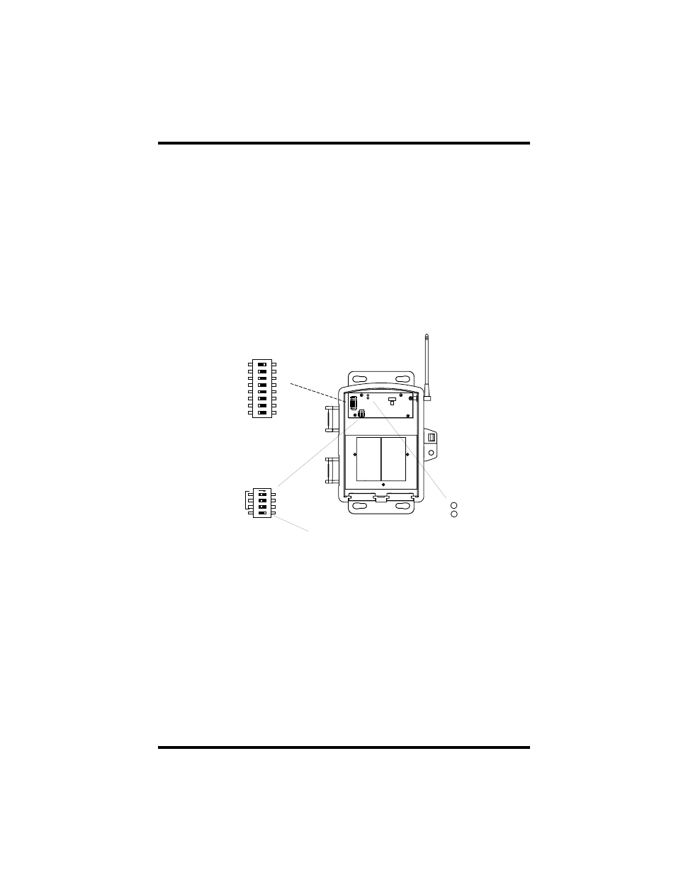
First off, open the repeater housing. Inside, you should see a green circuit
board in the upper part of the right-hand side of the box. Compare the circuit
board in your repeater with the picture below. You should be able to identify
the Transmitter ID DIP switch component with its eight switches on the left
edge of the board, the Repeater ID DIP switch, recognized by its four switches,
and finally the two test LEDs in the upper left part of the board.
The DIP switches are used to configure the repeater.
✦
If you’re using only one repeater, the Repeater ID DIP switches are not
required. Leave them at the factory settings (all off).
✦
Use the Transmitter ID DIP switches to select which Transmitter IDs to
repeat.
✦
For example, if you have one transmitter, say a Vantage Pro ISS
(#6320), transmitting on ID five (5), turn Transmitter ID DIP switch
five on and turn all others to off.
✦
For example, if you have two transmitters (and you could have up
to eight), say a Vantage Pro ISS (#6320) and a Wireless Temperature
Station (#6370), transmitting on IDs four (4) and eight (8), turn
Transmitter ID DIP switches four and eight to on and all others to
off.
ON
ON
1
2
3
4
5
6
7
8
Transmitter ID
DIP switch
TRANSMITTER
ID
TEST ON
1
234
ON
REPEATER
ID
TEST OFF
TX
RX
Repeater ID
DIP switch
TX
RX
Test LEDs
Test Switch
Transmitter ID Code Set to One (1)