JKS 4100 User Manual
Page 3
JKS4100
JKS Quicker Disconnect Installation
Page 3
To determine the proper location for the lower
mounting tab, temporarily slide the Upper End (G)
of Quicker Disconnect onto the Upper Stainless
Steel Post (C) and adjust angle of swaybar to Ac-
ceptable Range (0°-10°).
HINT: Refer to Step 6 on
next page for illustration of swaybar angle.
Temporarily insert the threaded end of Lower
Stainless Steel Post (L) into Weld-on Tab (J) and
secure with 1/2” Nylock Nut (K). Slide tab and post
assembly into Lower End (H) of Quicker Discon-
nect.
Choose the configuration for the Lower Mount-
ing Tab that allows the Quicker Disconnect to be
installed as close to vertical as possible. Length
of Quicker Disconnect may be adjusted as long
as it does NOT exceed Maximum Length of 9-3/8”
(measured from bushing centers).
Mark the location on the axle tube where Weld-on
Tab (J) will be installed.
4. MOUNT WELD-ON TAB TO AXLE TUBE
Remove tab and post assembly from Lower End
(H) of Quicker Disconnect and disassemble.
Remove paint from axle tube where Weld-on Tab
(J) will be mounted and clean area thoroughly.
Weld lower mounting tab to axle tube so that
Stainless Steel Post – when installed – is horizon-
tal or parallel with the ground.
Paint Weld-on Tab (J) and any bare metal on axle
tube with spray paint to prevent corrosion.
5. INSTALL LOWER TAPERED POST
Re-insert threaded end of Lower Stainless Steel
Post (L) into Weld-on Tab (J). Tapered end of post
must point forward or outboard, depending on the
mounting configuration chosen.
Secure Stainless Steel Post (L) with 1/2” Nylock
Nut (K), ensuring small Click Pin holes are hori-
zontal or parallel with ground.
Tighten 1/2” Nylock Nut (K) to 65 ft-lb. using a
torque wrench.
HINT: A small Philips head screw-
driver or punch inserted into the Click Pin hole
will enable you to prevent the Stainless Steel Post
from rotating when tightening the mounting bolt.
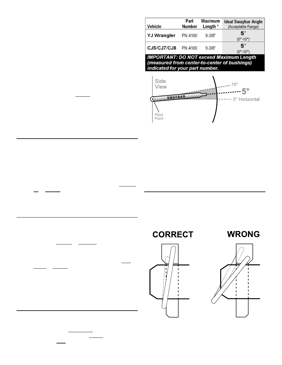
6. SET QUICKER DISCONNECT LENGTH
Adjust the length of your Quicker Disconnects until
swaybar is at the Ideal Angle or within Acceptable
Range. Vehicle must be at normal ride height and
located on level ground.
IMPORTANT: DO NOT exceed Maximum Length (mea-
sured from center-to-center of bushings) indicated for
your part number.
Once adjusted, lay Quicker Disconnects on a flat
surface and tighten Jam Nuts (M) firmly against
the Lower Ends (H).
IMPORTANT: Bushing cradles at both ends of Quicker
Disconnect must remain parallel with their respective
mounting posts when Jam Nut is tightened.
7. INSTALL QUICKER DISCONNECTS
Slide Upper End (G) of Quicker Disconnect onto
the Upper Stainless Steel Post (C) and Lower End
(H) onto Lower Stainless Steel Post (L).
Insert Click Pins (D) as illustrated to secure.
IMPORTANT: When properly installed, the ring on the
Click Pin will “snap” against the shaft of pin. When in-
stalled backwards, the ring does not fit snugly against
shaft.