HP XP P9500 Storage User Manual
Page 97
5.
Run the pairresync -swaps in the primary site on the other multi-target pair.
6.
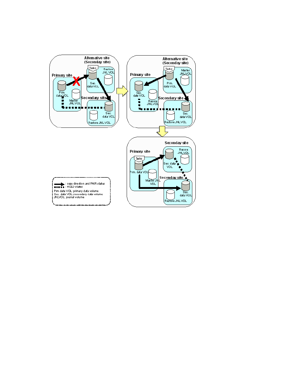
Resume business operations at the primary site.
Figure 13 Configuration when transferring business tasks from the Cnt Ac-J secondary site to the
primary site (delta resync operation is performed)
Recovery for 3 Cnt Ac-J/Cnt Ac-S data centers and 3 Cnt Ac-J data centers
All procedures described in the following sections apply to both 3 Cnt Ac-J/Cnt Ac-S data centers
and 3 Cnt Ac-J data center recovery.
Recovery procedures when Cnt Ac-J P-VOLs and S-VOLs are shared with Continuous Access
Synchronous can be more complex than general procedures.
The following topics provide recovery procedures for resuming host operations at a backup site
and then restoring the original system and configurations.
•
“Recovery for 3 Cnt Ac-J/Cnt Ac-S DC cascade configuration ” (page 97)
•
“Recovery for 3 Cnt Ac-J/Cnt Ac-S DC multi-target configuration ” (page 98)
•
“Recovery in a delta resync configuration” (page 99)
•
“Recovery in a 2DC configuration ” (page 101)
Use RAID Manager to perform all procedures.
Recovery for 3 Cnt Ac-J/Cnt Ac-S DC cascade configuration
Host operations are transferred to the Cnt Ac-S secondary volume (S-VOL) at the intermediate site
when a disaster or failure occurs in the primary site of a 3DC cascade configuration. The primary
site failure is corrected and brought back online, then either the cascade configuration is restored
or the multi-target configuration is created.
See
“3DC cascade configuration ” (page 141)
or
“3 Cnt Ac-J DC cascade configuration” (page 126)
for information and illustrations on the configuration covered in this procedure.
Recovery for 3 Cnt Ac-J/Cnt Ac-S data centers and 3 Cnt Ac-J data centers
97