1 devicenet module sk tu3dev, 1 devicenet module sk tu3-dev – NORD Drivesystems BU0080 User Manual
Page 9
2 Modules
9
2.1.1
DeviceNet module SK TU3-DEV
This DeviceNet module can be used for all types of SK 500E devices. It occupies the technology slot which
can then no longer be used for control and display modules. Alternatively, the SimpleBox SK CSX-0 can be
plugged on to the DeviceNet module and connected via the RS232/485 interface with the frequency inverter.
The DeviceNet module must be provided with an external 24V power supply. This DeviceNet participant can
therefore be identified by the master system even without a voltage supply to the frequency inverter. The data
required for this purpose are set using a rotary coding switch. This Bus data is read in when the 24V is applied
from the frequency inverter.
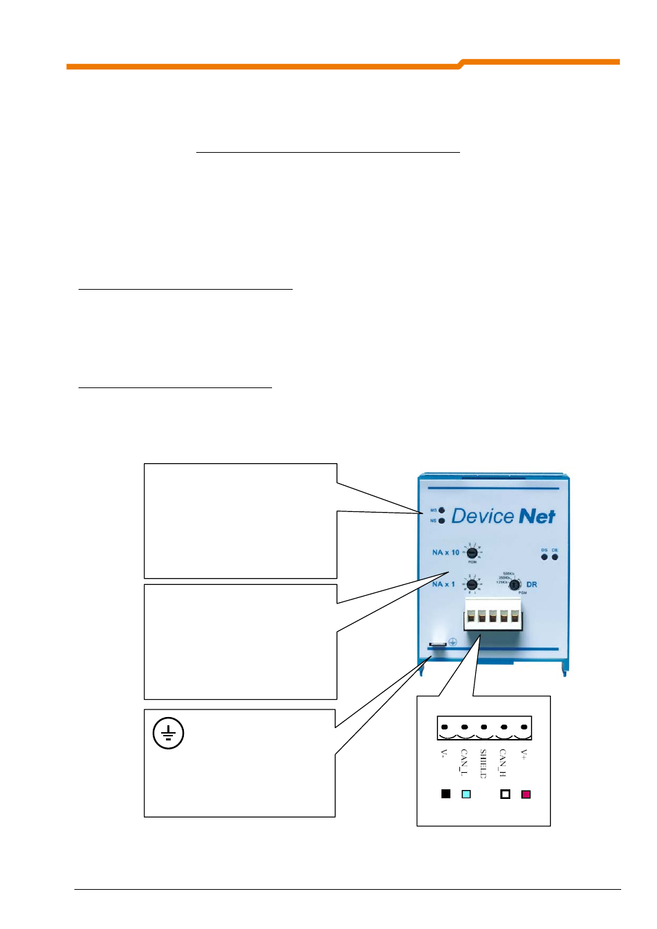
Supply voltage:
The supply voltage is 24V DC
±25% (pin 1 = V-, pin 5 = V+ (from left to right)). The connection is made via the
5-pin open-style plug connector. (See illustration below)
Setting the node address: (See Section.5.4)
The node address (0...63) can be set with the rotary switches NA x 1 and NA x 10:
Example: Node address = 50 dec = NAx 1 = 0, NAx 10 = 5
If the node address is set to a value greater than 63, the value from the parameter (P515[-01]) of the frequency
inverter is used as the node address.
Setting the baud rate: (See Section 5.4)
The baud rate can be set using the rotary switch DR (125kBit/s...500kBit/s). If a value in the PGM range is set,
the value from parameter (P514) of the frequency inverter is used as the baud rate.
Note: The settings made using the rotary coding switch are not transferred to the frequency inverter or saved.
DeviceNet status LEDs
MS (red/green)
Æ Modul status
NS (red/green)
Æ Mains (bus) status
DS (green)
Æ Module status
DE (red)
Æ
Module error
Further details in Chap. 5.3
Shielding terminal:
Connection to PE of the frequency
inverter to suppress interference in the
Bus lines
rotary coding switch
DR
Æ Baud rate
NA
Æ Node address
Further details in Chap. 5.4