4 bus configuration, 1 laying the bus cables, 2 cable length – NORD Drivesystems BU0080 User Manual
Page 17: 3 cable layout and shielding (emc measures)
4 Bus structure
17
4 Bus configuration
A DeviceNet network consists of a maximum of 64 participants (nodes) and is based on a linear topology. The
number of participants is dependent on the driver modules (standard approx. 100 nodes). Repeaters must be
used for a high number of nodes.
Shielded, 5-wire cables according to the DeviceNet specification must be used.
4.1 Laying the bus cables
In an industrial environment the correct installation of the bus system is particularly important in order to
reduce potential interference. The following points are designed to help prevent interference and problems
right from the start. The installation guidelines are not complete and applicable safety and accident prevention
guidelines must be complied with.
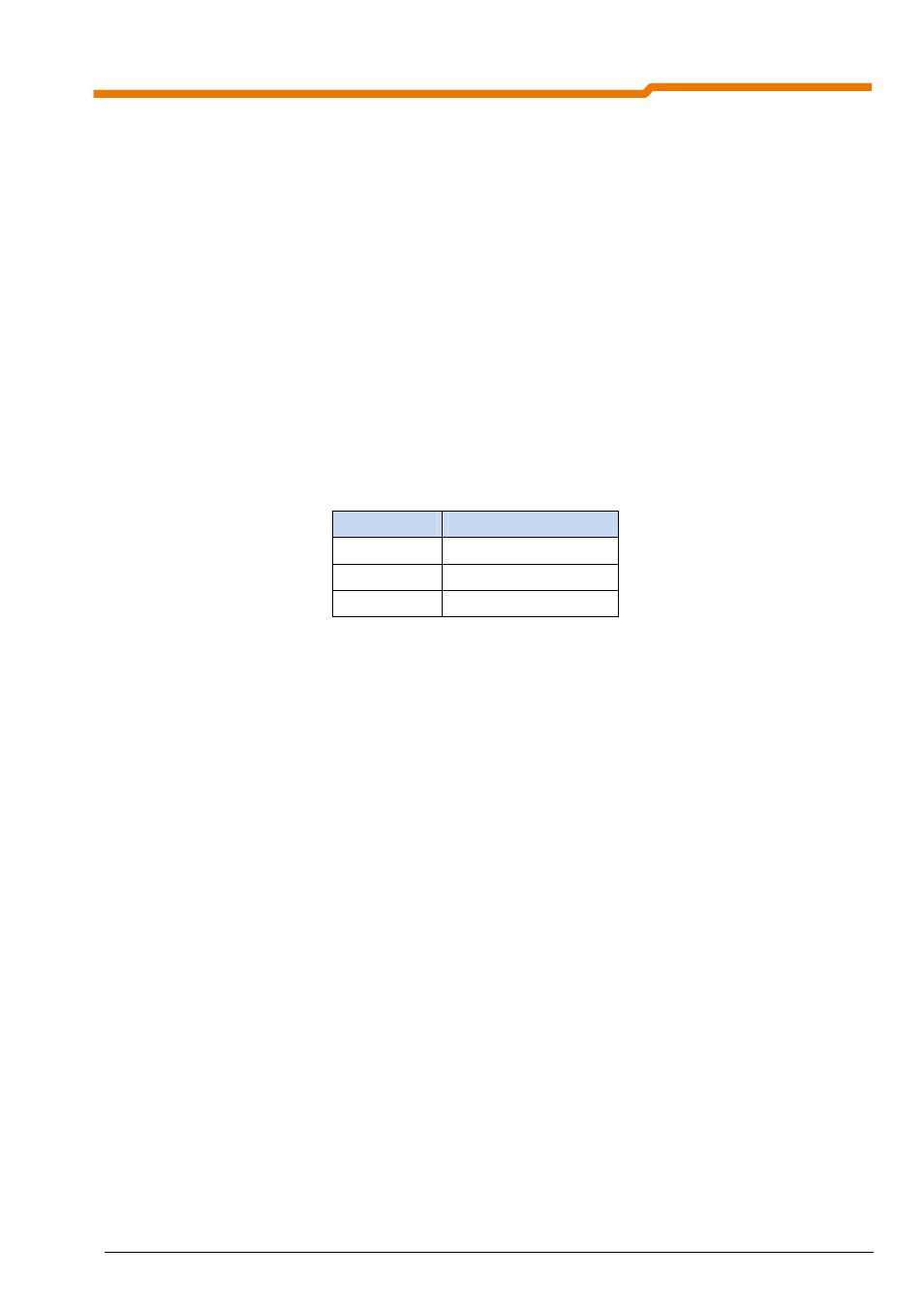
4.2 Cable length
The guaranteed transfer speeds or transfer distances can only be achieved without errors if the specific cable
parameters are complied with.
2-wire shielded copper cable should be used.
Bus length
Maximum baud rate
up to 500m
125 KBit/s
up to 250m
250 KBit/s
up to 100m
500 KBit/s
The maximum length of spur cables depends on the cable material and the selected baud rate. These can be
seen in the DeviceNet specification.
4.3 Cable layout and shielding (EMC measures)
Without EMC measures, high frequency interference, which is mainly caused by switching processes or
lightning often has the effect of interfering with electronic components in the bus participants and error-free
operation is no longer ensured.
Appropriate shielding of the bus cable reduces electrical interference which can arise in an industrial
environment.
Bus lines should be laid with a minimum spacing of 20 cm to other lines which carry a voltage higher than 60
V. This applies to lines laid inside and outside of control cabinets.
Note: If earthing potential values are different, transient current may flow through shielding which is
connected on both sides. This may be a danger to electronic components. Differences in potential must
be reduced using sufficient potential equalisation.
With the NORDAC SK 500E and SK 700E series, the PE terminal of the module must be connected to the PE of
the frequency inverter (e.g. shielding angle)