4 process data (pzd), 1 process data for sk 300e/700e/750e, 2 process data for sk 500e (entire series) – NORD Drivesystems BU0080 User Manual
Page 28
NORDAC DeviceNet Manual
28
BU
0080
GB
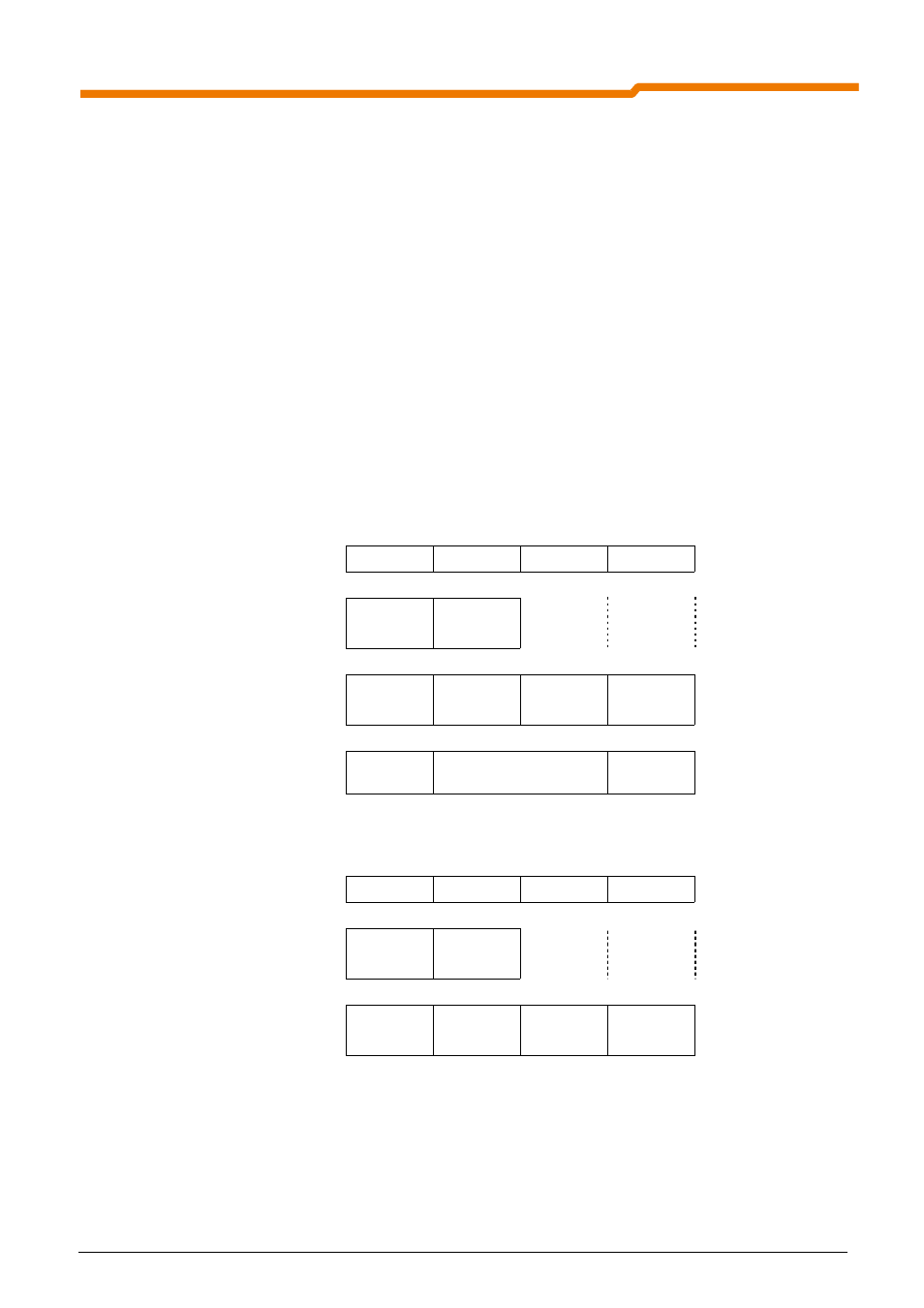
6.4 Process data (PZD)
In the process data area (PZD) , control words and setpoints are transferred from the Master to the Slave
(frequency inverter) and in return, status words and actual values are sent from the Slave to the Master. The
structure of the PZD area is always the same in terms of the sequence of its elements (words), however,
dependent upon direction of data Master
⇒ Slave / Slave ⇒ Master, it is described differently.
The process data area of the reference data has the following structure:
- STW:
Control Word; length 16 bit, order telegram
contains control bits (e.g. enable, rapid stop, error acknowledgement)
- ZSW: Status Word; length 16 bit, response telegram
contains status bits (e.g. FI running, fault)
- SW1..3: Setpoints; maximum 3 possible, 16 or 32 bit, order telegram
e.g. frequency setpoint, position setpoint, torque setpoint
- IW1..3: Actual Values; maximum 3 possible, 16 or 32 bit, response telegram
e.g. actual frequency value, actual position value, actual torque value
6.4.1
Process data for SK 300E/700E/750E
1st word
2nd word
3rd word
4th word
PZD area with
1x16 bit setpoint
STW
ZSW
SW1
IW1
PZD area with up to 3
16 bit setpoints
STW
ZSW
SW1
IW1
SW3
IW3
SW2
IW2
PZD area with 1x 32-Bit setpoint
and 1x 16-Bit
STW
ZSW
SW1
IW1
SW2
IW2
6.4.2
Process data for SK 500E (entire series)
1st word
2nd word
3rd word
4th word
PZD area with
1x16 bit setpoint
STW
ZSW
SW1
IW1
PZD area with up to 3
16 bit setpoints
STW
ZSW
SW1
IW1
SW2
IW2
SW3
IW3
Note: 32-Bit setpoints consist of High and Low words (16-Bit each).