6 data transmission, 1 i/o messages - operating modes, 2 assembly – NORD Drivesystems BU0080 User Manual
Page 27: 3 ac profile
6 Data transmission
27
6 Data transmission
6.1 I/O Messages - operating modes
Via I/O messages the control data is transmitted from the Master to the frequency inverter, or status data is
transmitted from the frequency inverter to the Master.
Transmission can be cyclically (Polling 7 Cyclic) or event controlled (Change Of State/Bit-Strobe). With the SK
700E series, 4 or 8 Bytes of data are transmitted.
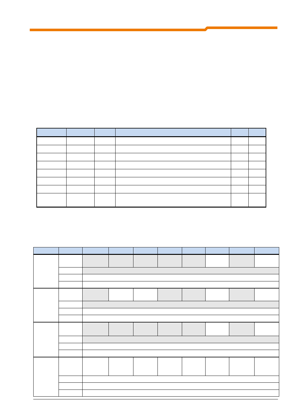
6.2 Assembly
(P551) sets whether the AC profile is active. Via (P507) the active AC Drive assembly instance is selected or
the data length is specified (See table).
The following assembly instances are available for I/O messages:
Assembly
Profile
Length
P551
P507
20
AC-DRIVE 4 Byte
Control word + setpoint speed
1
1
21
AC-DRIVE 4 Byte
Control word + setpoint speed
1
2
70
AC-DRIVE 4 Byte
Status word + actual speed
1
1
71
AC-DRIVE 4 Byte
Status word + actual speed
1
2
100
NORDAC 4 Byte
Control word + setpoint 1
0
1
101
NORDAC 8 Byte
Control word + setpoint 1 + setpoint 2 + setpoint 3
0
2
110
NORDAC 4 Byte
Status word + actual value 1
0
1
111 NORDAC
8
Byte
Status word + actual value 1 + actual value 2 +
actual value 3
0 2
6.3 AC Profile
If the AC Profile is activated (P551=On), the assembly instances 10, 21, 70 and 71 are valid. The process data
has the following meaning:
Instance
Byte
Bit 7
Bit 6
Bit 5
Bit 4
Bit 3
Bit 2
Bit 1
Bit 0
0
Fault
Reset
Run
Forward
1
2
Setpoint speed [min
-1
](Low Byte)
20
3
Setpoint speed [min
-1
](High Byte)
0
NetRef
NetCtrl
Fault
Reset
Run
Forward
1
2
Setpoint speed [min
-1
](Low Byte)
21
3
Setpoint speed [min
-1
](High Byte)
0
Run
1
Fault
1
2 Actual
speed
[min
-1
](Low Byte)
70
3 Actual
speed
[min
-1
](High Byte)
0
At
Referenc
e
Ref from
Net
Ctrl from
Net
Ready
Run 2
Run 1
Warning
Fault
1 Drive
State
2 Actual
speed
[min
-1
](Low Byte)
71
3 Actual
speed
[min
-1
](High Byte)