3 led display, 4 rotary coding switch, Section.5.4 ) – NORD Drivesystems BU0080 User Manual
Page 26: Devicenet status leds: (see section.5.3 ), S:(see section 5.4), Section 5.4
NORDAC DeviceNet Manual
26
BU
0080
GB
5.3 LED display
The status of the DeviceNet technology unit is shown by a total of 4 LEDs:
• MS/NS: DeviceNet status
• DS/DE: Module status
MS (red/green): DeviceNet module status
Display
Significance
Off
No power supply to the module
Green on
Module is ready
Green flashing
Module is on standby
Red flashing
Acknowledgeable error
Red on
Non-acknowledgeable error, module may have to be replaced
NS (red/green): DeviceNet network status
Display
Significance
Off
Module is not online:
- No power supply to the module
- The module could not perform the Dup_MAC_ID test
Green flashing
Module is online and has performed the Dup_MAC_ID test, but has not carried
out the setup of communication with other participants
Green on
The module is online and has a connection with a Master
Red flashing
One or more I/O connections are in a timeout status
Red on
The module has detected an error, so that no communication is possible, e.g.
Bus Off, Dup_MAC-ID test error)
DS (green): Module status
Display
Significance
Off
No voltage supply
Flashing
Initialisation (init. phase)
On
Module OK
DE (red): Module status
Display
Significance
Off No
error
Rapid flashing (0.2s)
Initialisation phase
Slow flashing (0.5s)
Timeout error
Isolated flashing
Inverter error (see frequency inverter instructions)
On
System error, e.g. plug contact not correct
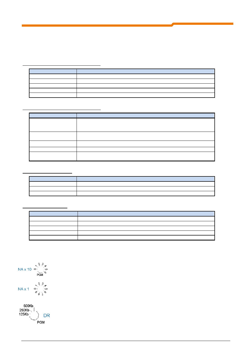
5.4 Rotary coding switch
The node address can be set with the rotary switches NA x 1 and NA x 10:
Example: Node address = 50 dec = NAx 1 = 0, NAx 10 = 5
If the node address is set to a value greater than 63, the value from the
parameter (P515) of the frequency inverter is used as the node address.
The baud rate can be set using the rotary switch DR (125kBit/s...500kBit/s). If a
value in the PGM range is set, the value from parameter (P514) of the frequency
inverter is used as the baud rate.