3 nordac trio sk 300e, 1 devicenet module sk tu2dev, 1 devicenet module sk tu2-dev – NORD Drivesystems BU0080 User Manual
Page 14
NORDAC DeviceNet Manual
14
BU
0080
GB
2.3 NORDAC trio SK 300E
With the combination of technology units and customer units (interfaces with digital and analog inputs) the
NORDAC trio SK 300E can easily be extended to cater for the requirements of a wide range of different
applications.
2.3.1
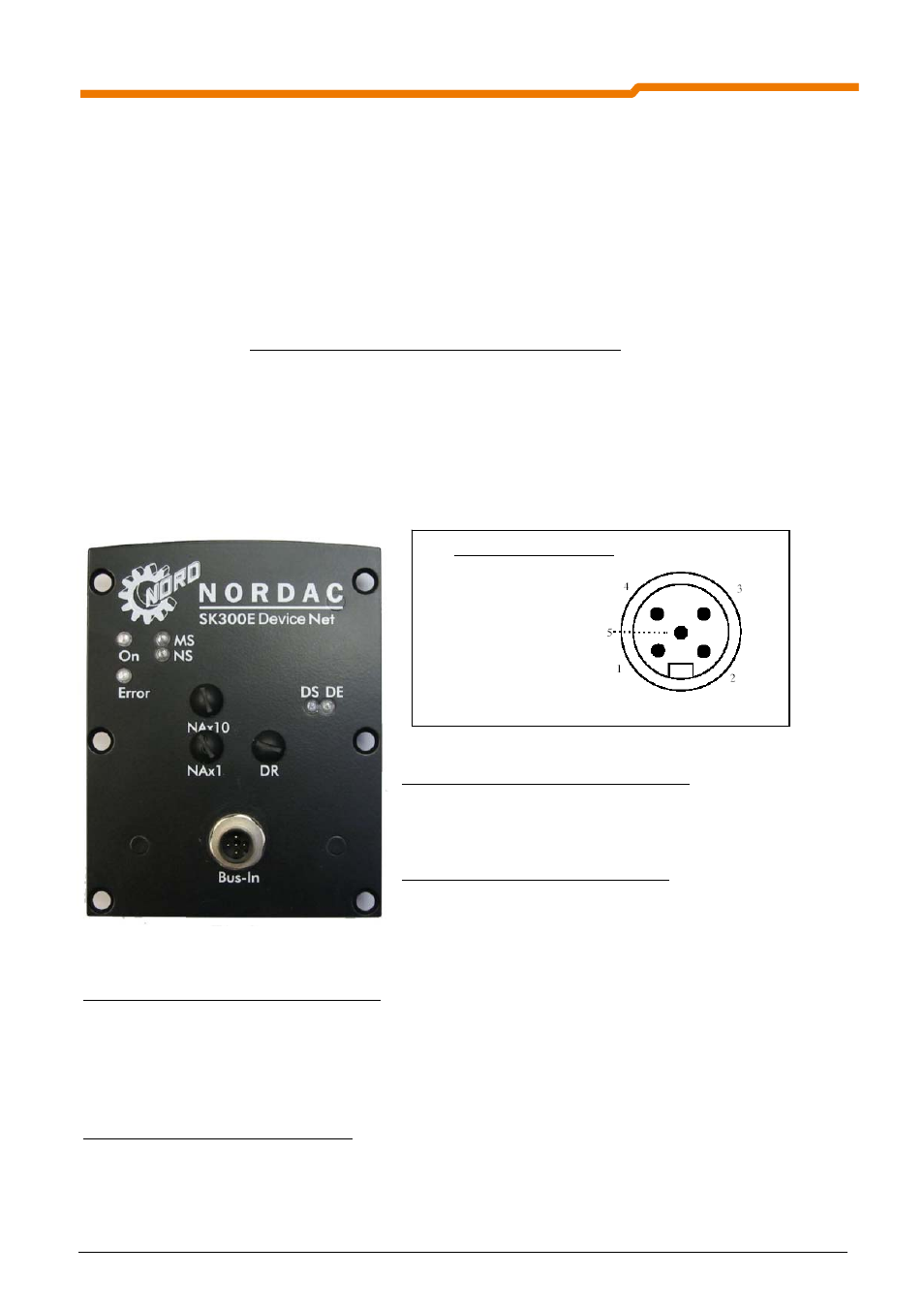
DeviceNet module SK TU2-DEV
This DeviceNet module can be used for all types of SK 300E and SK 750E devices. With the SK 300E it
occupies the technology slot which can then no longer be used for control and display modules. Alternatively, a
hand-held parameter box, SK PAR-2H can be connected (SK PAR-3H with adapter) to the frequency inverter
via a standard RS485 interface (M12).
The DeviceNet module must be provided with an external 24V power supply. This DeviceNet participant can
therefore be identified by the master system even without a voltage supply to the frequency inverter. The data
required for this purpose are set using a rotary coding switch. This Bus data is read in when the 24V is applied
from the frequency inverter.
Supply voltage:
The supply voltage is 24V DC
±25% (pin 1 = V-, pin 5 = V+ (from left to right)). The connection is made via the
5-pin open-style plug connector. (See illustration below)
DeviceNet status LEDs: (See Section 5.3)
MS (red/green): Module status
MS (red/green)
Mains status
Module status LEDs (See Section 5.3):
DS (green):
Module status
DE (red):
Module error
Setting the node address:(See Section 5.4)
The node address (0...63) can be set with the rotary switches NA x 1 and NA x 10:
Example: Node address = 50 dec = NAx 1 = 0, NAx 10 = 5
If the node address is set to a value greater than 63, the value from the parameter (P515) of the frequency
inverter is used as the node address.
Setting the baud rate:(See Section 5.4)
The baud rate can be set using the rotary switch DR (125kBit/s...500kBit/s). If a value in the PGM range is set,
the value from parameter (P514) of the frequency inverter is used as the baud rate.
Connector assignment:
1 Shield
2 V+
3 V -
4 CAN_H
5 CAN_L