2 installing the technology unit – NORD Drivesystems BU0080 User Manual
Page 15
2 Modules
15
2.3.2
Installing the technology unit
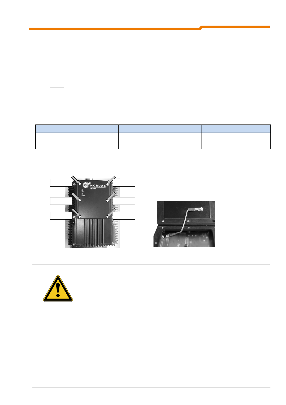
Installation: the technology units must be installed as follows:
1. Switch off the mains voltage, observe the waiting period.
2. Undo the 6 fastening screws on the blind plate and remove the blind plate (see left illustration).
3. Attach the PE connection on the inside of the technology unit being mounted (see right illustration). Fit
the seal together with the technology unit on the surface of the frequency inverter. Ensure that the
connector strip has full contact.
4. Lightly tighten all 6 fastening screws.
5. Now tighten the 6 fastening screws in the specified sequence from 1 to 6 (see Fig. 1 on next page) and
with the torque given in the table.
Frequency inverter size
Screw size
Tightening torque
Size 1
Size 2
M4 x 8
1.5Nm ± 20%
Technology unit fastening screws
PE connection on the technology unit
Screw 3
Screw 4
Screw 6
Screw 2
Screw 1
Screw 5
WARNING
NOTE
Modules must not be inserted or removed unless the device is free of voltage. The slots may
only be used for the intended modules.
Installation of a technology unit separate from the frequency inverter is not possible. It must be
connected directly to the frequency inverter.
Operation is not permitted if there is no secure PE connection to the frequency inverter and to
the technology unit!