Serial communication options – FUTEK IPM500 (D500) Digital Display User Manual
Page 41
41
RS-232
g
h
j
RJ11
J
232
f g
e
RJ11
RS-232
Modbus
b
a
c
d
e
RJ45
RJ45
f
18. SERIAL COMMUNICATION OPTIONS
A variety of optional serial communications boards may be connected to the meter main board
at plug position P13 (middle position). These include RS-232, RS-485, RS-485 Modbus, USB,
and USB to RS-485.
Both boards feature dual connectors, which are wired in parallel to allow daisy chaining of
addressable meters. Three serial communication protocols are : Custom ASCII, Modbus RTU,
and Modbus ASCII. Multiple meters on the same serial communication line requires RS485 or
RS485-Modbus boards. The USB to RS485 converter replaces the RS485 board in one of the
meters to provide a direct USB connection to a PC or PLC without an external converter.
LOADING USB AND USB/RS-485 DRIVERS
Using a USB cable
with Type A and Type B connectors, connect the meter to the computer.
The computer will display “Found new Hardware” followed by “Welcome to the ‘Found new
Hardware Wizard’ ”. Follow the instructions for installation from a CD
When the installation is complete
, use the Device Manager to determine the Com port
number. To get to Device Manger, go to Control Panel, click on System, click on Hardware tab
and then click on Device Manager. Go down the device list and click on Ports (COM & LPT)
and USB serial port (com #). Note the com port # for use with communications to your IPM
meter, and exit Control Panel
If you need to change the Com port,
right-click on USB serial port (com #), then click on
Properties, Port settings and Advanced. Change the port to the desired number and click OK,
then exit Control Panel.
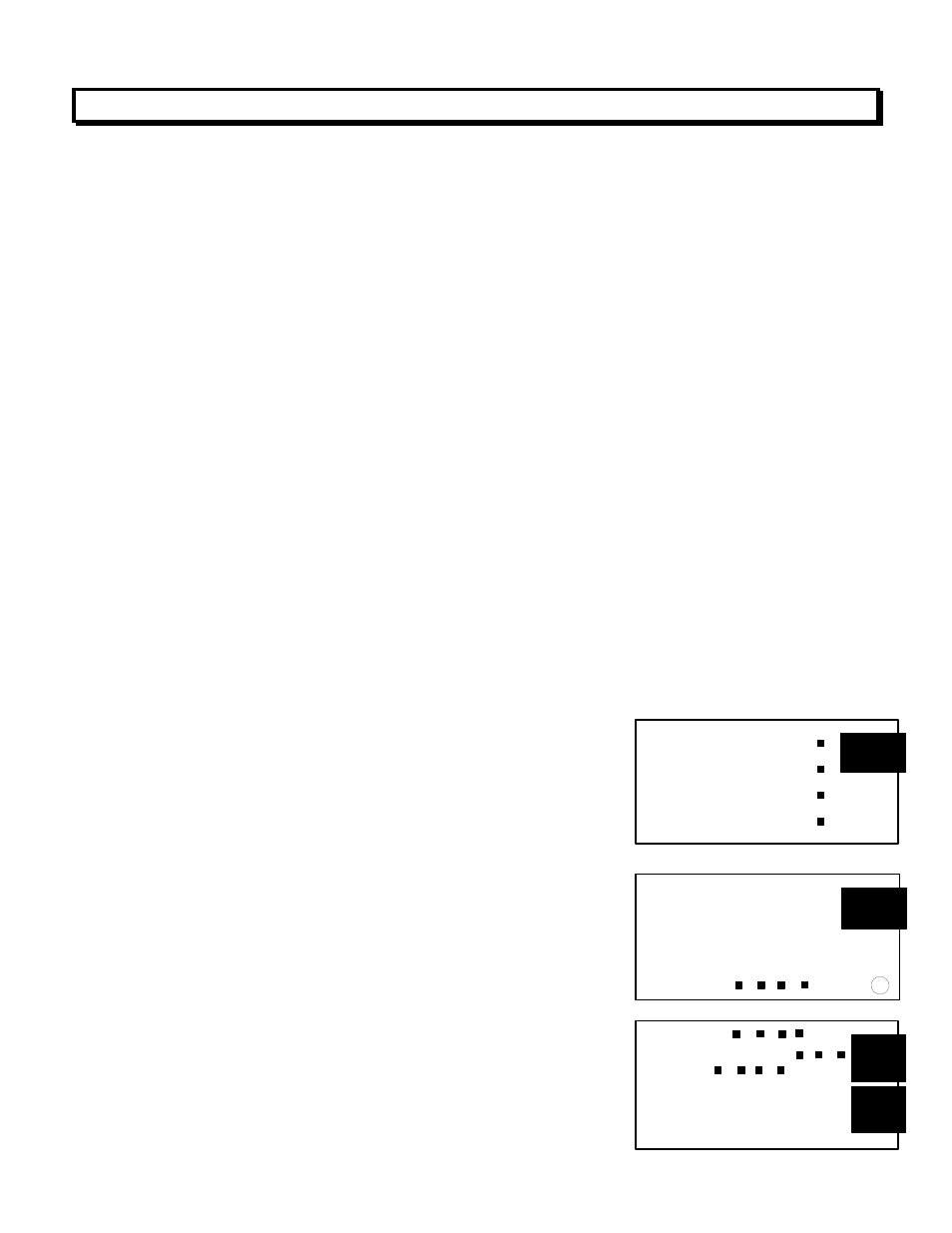
BOARD SETUP VIA JUMPERS
USB Board
No jumpers required
RS232 Board
g
- Normal operation.
h
- Slave display operation to RS232 from another meter.
J
- Pull-up resistor on RTS line.
Note
: The board is shipped with jumpers g and j installed.
RS232 Board Rev J
e
- Normal operation.
f
- Slave display operation to RS232 from another meter.
g
- Pull-up resistor on RTS line.
Note
: The board is shipped with jumpers e and g installed
RS485 and RS485-Modbus Boards
Full Duplex Operation
b & e
- Bias jumpers should be installed on 1 board.
a & d
- Installed on last meter in long cable run.