FUTEK IPM500 (D500) Digital Display User Manual
Page 32
32
15. RTD & RESISTANCE INPUT
RTD and resistance measurement utilizes the same signal conditioner board, which can be
configured via jumpers for four RTD types (100Ω platinum with DIN or ANSI alpha, 10Ω cop-
per, 120Ω nickel) or five resistance ranges (from 20.000Ω to 200.00 kΩ). All ranges are factory
calibrated with calibration factors stored in EEPROM on the signal conditioner board. The
meter software recognizes the board and will bring up the appropriate menu items for it;
however, it does not recognize the jumper settings. With RTDs, display in °C or °F and
resolution of 1°, 0.1° or 0.01° are user programmable. 0.01° resolution should only be used for
relative readings, not absolute readings, and with software selectable digital filtering.
The addition of a relay output board turns the meter from an indicator into an on/off controller.
Please see further manual sections for setup of the following features: relay output (Section
16), analog output (17), and communications (18).
SIGNAL CONDITIONER BOARD SETUP VIA JUMPERS
1.
Use 2.5 mm (0.1") jumpers.
2.
Store spare jumpers on an unused jumper post.
SCALE & OFFSET SETUP
Scale
is normally set to 1.0000. Scale can be used as an RTD correction when actual
resistance is other than nominal, as stated on the RTD calibration sheet. For a Pt100 RTD,
divide 100 by the stated resistance at 0°C. For example, for a 99.04 ohm RTD, scale should be
set to 100 / 99.04 = 1.0097.
Offset
is normally set to 0000.0. If °C is selected for an RTD, entering an offset of 0273.2 will
change the display to Kelvin. If °F is selected, entering 0459.7 will change the display to
Rankin.
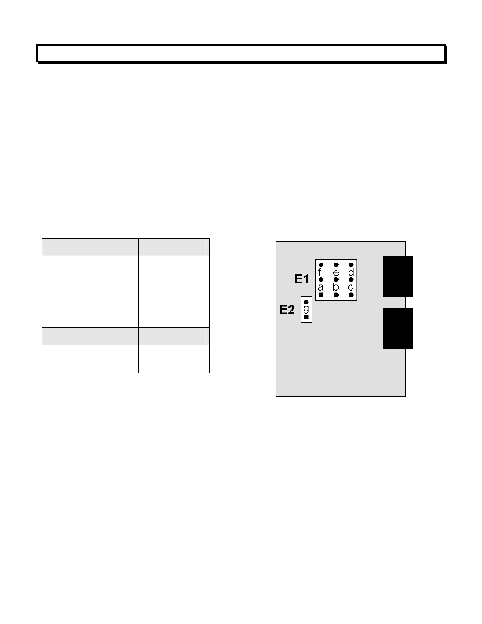
RTD Type or Ohms
E1 Jumper
Pt100, Ni120
Cu10, 20 Ω
200 Ω
2000 Ω
20000 Ω
200 kΩ
a
b
c
d
e
f
Connection
E2 Jumper
2 or 4 wire
3 wire
none
g