Installation – Dwyer 32DZ User Manual
Page 3
June, 2000
Page 3 of 40
949-1318
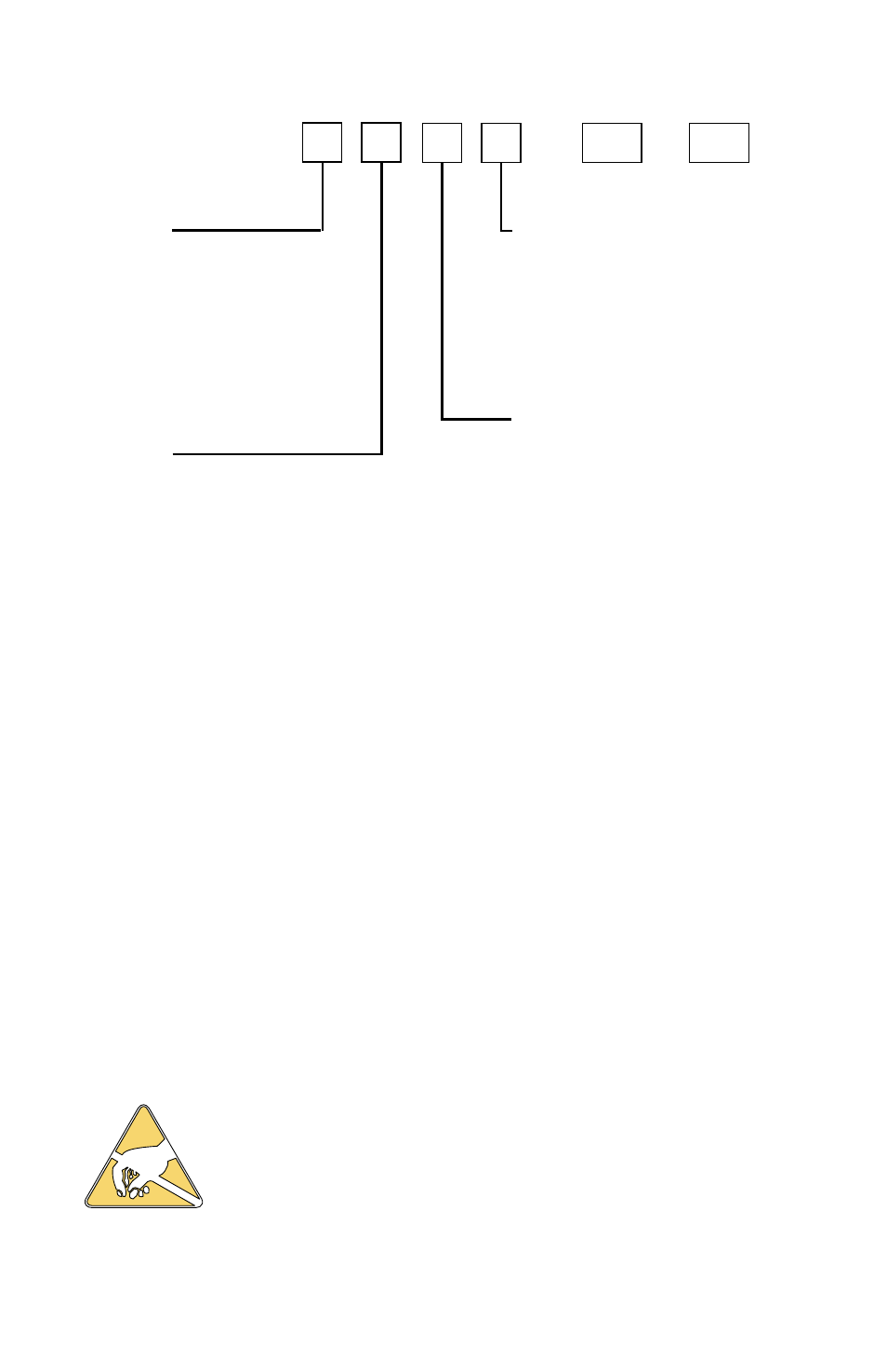
MODEL IDENTIFICATION
Model 3 2 D Z
—
Output B
1 = SSR
2 = Switched Voltage 5 Vdc
3 = Relay
8 = DC SSR
Output A
1 = SSR
2 = Switched Voltage 5 Vdc
3 = Relay
5 = Proportional current
8 = DC SSR
Options
INSTALLATION
All models are designed for mounting in an enclosed panel. Select
the position desired for the instrument on the panel. If more than one
instrument is required, maintain the minimum of spacing require-
ments as shown on the drawing opposite. Closer spacing will
structurally weaken the panel, and invalidate the IP66, UL type 4
rating of the panel.
It is not necessary to remove the instrument chas-
sis from the housing for installation. If the instru-
ment chassis is removed from the housing, you
must follow the ANSI/IPC-A-610 standard for han-
dling electronic assemblies to avoid damage from
Electro-Static Discharge (ESD). Failure to properly
handle the instrument may cause damage to the
instrument.
Input 1
1 = Thermocouple J,K,E,L,N
2 = Thermocouple T,R,S,B,C
3 = 100 and 120 ohm RTDs
4 = 1000 Ohm RTD
5 = Current, 0 or 4 to 20 mA
6 = Voltage, 0 or 2 to 10 V
Input 2
1 = Thermocouple J,K,E,L,N
2 = Thermocouple T,R,S,B,C
3 = 100 and 120 ohm RTDs
4 = 1000 Ohm RTD
5 = Current, 0 or 4 to 20 mA
6 = Voltage, 0 or 2 to 10 V
Options:
992
RS-485 Serial Communications. Allows remote computer to read
and write all control parameters.
9502
12 - 24 Vdc/Vac 50-400Hz power supply (control operates on low
voltage equipment).