Electrical connections – KROHNE OPTISENS MAC 080 EN User Manual
Page 18
4
ELECTRICAL CONNECTIONS
18
OPTISENS MAC 080
www.krohne.com
01/2010 - MA MAC 080 R02 en
Description of terminals
Sensor
The sensors are connected to the converter via the M12 socket 5 at the lower side of the
converter housing using 10 m / 33 ft cables which are attached to the sensor. If the standard
cable length is not sufficient several cables may be connected in series. The maximum length is
100 m / 328 ft.
In the event that more than one sensor is connected to the same converter, then the junction box
is needed. Furthermore, for the connection of 3...4 sensors an extra 4...20 mA module or a
Profibus DP module must be installed in the converter to transfer the measuring results to a
SCADA or DCS system.
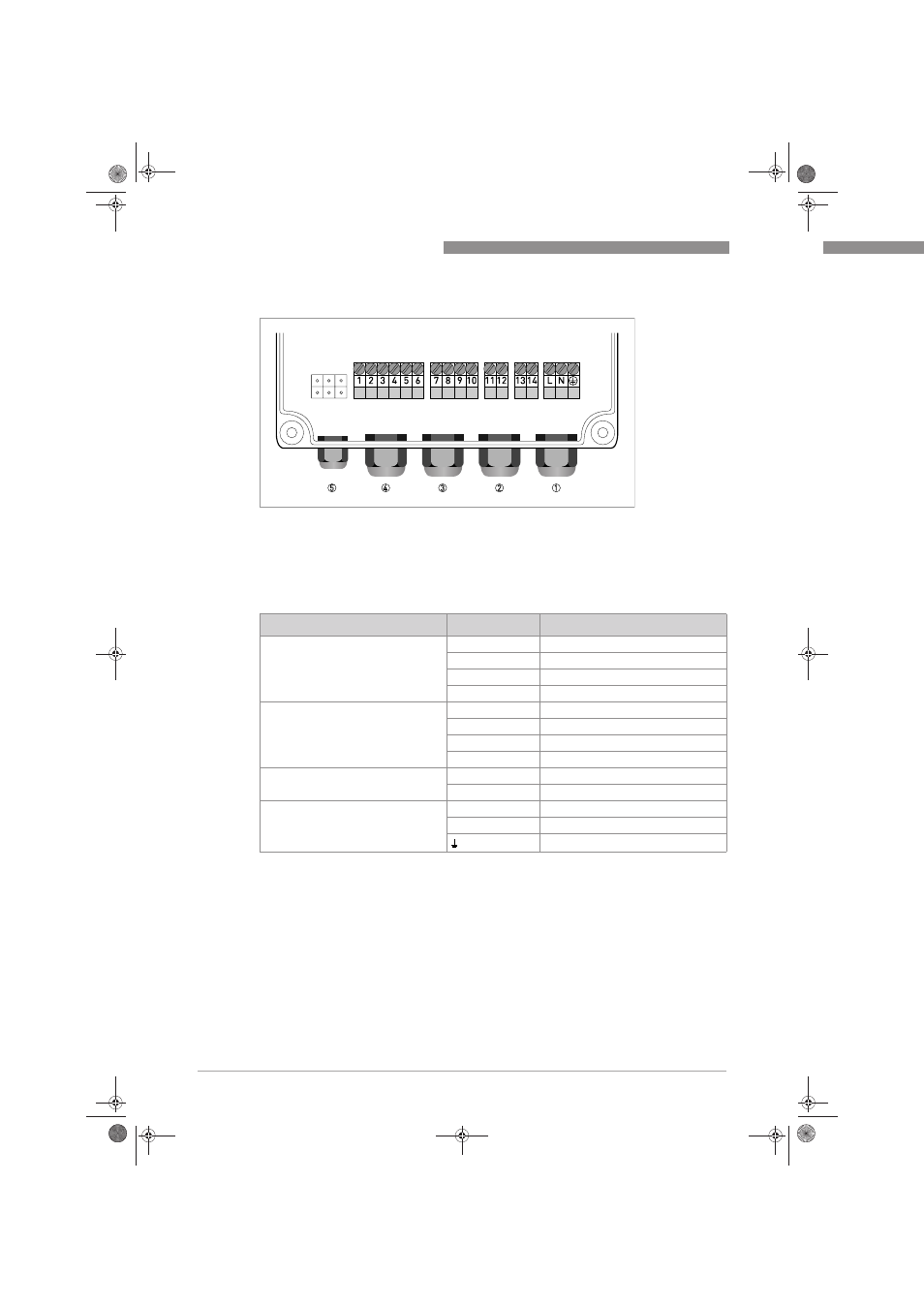
Figure 4-1: Terminals
1 M20 cable feedthrough for connection of power
2 M20 cable feedthrough for connection of relays (terminals 11...14)
3 M20 cable feedthrough for connection of 4...20 mA outputs (terminals 7...10)
4 M20 cable feedthrough for connection of digital inputs (terminals 1...6)
5 M12 socket for connection of one sensor or 2...4 sensors with a junction box
Description
Terminal
Function
Digital inputs 4
1, 2, 3
Digital in
4
-
5
+24 VDC
6
Signal ground SG
4...20 mA outputs 3
7
Channel 1, 4...20 mA neg.
8
Channel 1, 4...20 mA pos.
9
Channel 2, 4...20 mA neg.
10
Channel 2, 4...20 mA pos.
Relays 2
11, 12
Relay 1
13, 14
Relay 2
Power 1
L
Load or power
N
Neutral
Protective Earth (PE)
.book Page 18 Tuesday, January 19, 2010 1:07 PM