B.15 input:ramp command, Figure b-2. timing for inp:ramp, B.15 – KEPCO EL Series Electronic Load Operator Manual P/N 243-1295 Firmware Version 3.87 to 3.xx User Manual
Page 67: Input, Inp:ramp
SERIES EL 022013
B-5
B.15 INPut:RAMP COMMAND
INP:RAMP
Syntax:
Short Form: INP:RAMP
Long Form: INPut:RAMP
where
Description: Establishes a ramp to reach operating mode setpoint after engaging the load. When the load is
engaged, this command establishes the time it takes to attain the operating mode setpoint value. For
current and conductance modes, the ramp starts at zero and increases in even steps over the duration
established by
If the input ramp time is set to a number between 1 and 10,000, the ramp occurs when either a) the
LOAD switch is pressed to engage the load or b) when input voltage is lost, then rises above the cutoff
point while INP:CUT:VOLT (see PAR. B.13) is active. To turn off this ramp, send INP:RAMP 0. Setting
INP:CUT:VOLT to any value will disable the output and reduce overshoot at the start of the ramp.
This command operates in conjunction with SYST:RAMP (see PAR. B.106) which establishes a ramp
that is effective when the output changes state. If SYST:RAMP is in use, the ramp introduced by
INP:RAMP will be the larger of the times set by INP:RAMP and SYST:RAMP.
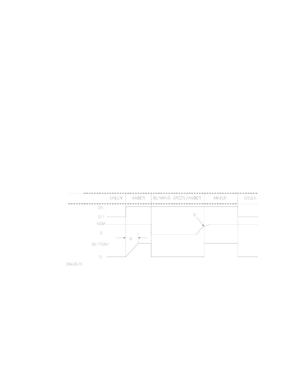
Figure B-2 shows the timing for INP:RAMP. The initial conditions are: the load is disengaged, LOAD
indicator shows green, input voltage is present, and the output is 0 for current or conductance, maxi-
mum for voltage or resistance. Sending INP? at this point returns 0, indicating the load is disengaged.
When the LOAD switch is pressed or INP:ON is received, the LOAD indicator changes to amber, the
load is engaged and the input ramps to the setpoint value within the time established by INP:RAMP
(A, Figure B-2). Sending INP? returns 1 (on).
FIGURE B-2. TIMING FOR INP:RAMP
If input voltage from the UUT (unit under test) is subsequently lost, the output is shorted (all FET’s are
on). When input voltage recovers, the input changes from a short to the proper setpoint in a time
determined by the SYST:DAMP command, the source capabilities of the UUT and the cabling
between the load and the UUT. To maintain a ramp and eliminate any overshoot, ensure that
INP:CUT:VOLT is set to some value to enable the ramp on this condition. Pressing the LOAD switch
disengages the load; the LOAD indicator turns green and sending INP? returns 0 (disengaged).
INPUT STATE
(LOAD SWITCH)
LOAD
INDICATOR
OUTPUT
(CURRENT OR
CONDUCTANCE)
INPUT
VOLTAGE
A = TIME DETERMINED BY INP:RAMP
B = VALUE DETERMINED BY INP:CUT:VOLT