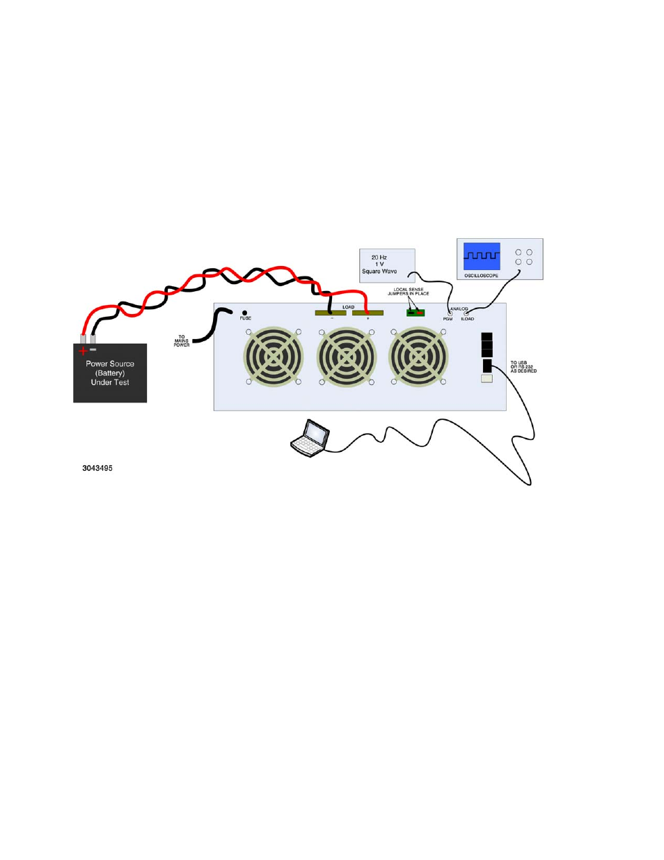
Figure 3-5. damping measurement setup, 2 recommended damping adjustment procedure, Recommended damping adjustment procedure -20 – KEPCO EL Series Electronic Load Operator Manual P/N 243-1295 Firmware Version 3.87 to 3.xx User Manual
Page 56: Damping measurement setup -20, R. 3.14.2
3-20
SERIES EL 022013
special situation, damping adjustments are best made using a test set up as shown in Figure 3-
5.
Figure 3-6 shows various waveforms that may appear at the current monitor output (I-Load)
when the load is connected to a high current source and the current drawn from the source
changes rapidly following a square wave (or pulse) source connected to the E-Load input. Fig-
ure 3-6 shows the effects of changing both the System Damping and the Mode Damping. The
exact waveforms that will be seen are highly dependent on the nature of the source, the inter-
connecting cables and the various damping setting.
FIGURE 3-5. DAMPING MEASUREMENT SETUP
3.14.2
RECOMMENDED DAMPING ADJUSTMENT PROCEDURE
Damping adjustments are made using the SCPI Commands found in Appendix B via either the
RS 232 or USB remote interface.
• System Damping. Use SYST:DAMP command (see PAR. B.93).
• Mode Damping. Use SYST:PFM:DAMP (see PAR. B.102).
Figure 3-6 shows sample waveforms of a properly damped EL (A) and an improperly damped
EL (B, C, D). The goal is to attain a waveform looking like A. This may not be possible and the
best that can be accomplished is C with the smallest overshoots. The waveform can be