Figure 3-6. damping waveforms, Damping waveforms -21, 6 sh – KEPCO EL Series Electronic Load Operator Manual P/N 243-1295 Firmware Version 3.87 to 3.xx User Manual
Page 57
SERIES EL 022013
3-21
observed using an oscilloscope connected to the ILOAD connector (Figure 3-5) or pin 1 (pin 15
return) of the Analog Control connector for dual channel units.
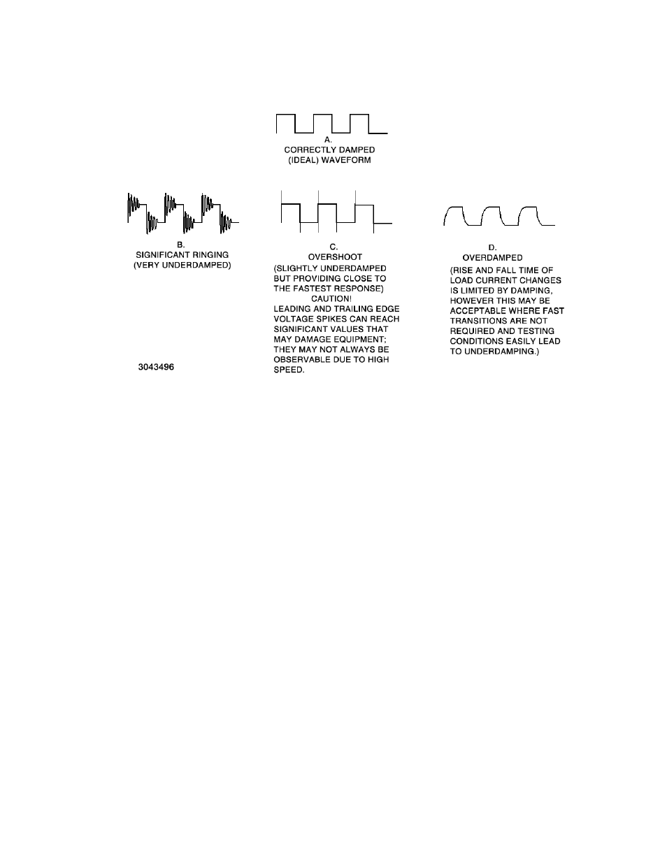
FIGURE 3-6. DAMPING WAVEFORMS
Before starting to adjust damping, send SYST:RAMP 0. NOTE: Ramps must be turned off
before adjusting damping, otherwise the unit will generate an overdamped waveform
similar to D.
When modifying the damping settings, a good approach is to start with SYST:DAMP 5 and
SYST:PFM:DAMP set to 4. SYST:DAMP is the coarse adjustment: higher numbers cause over-
damping and lower numbers cause significant ringing. If the waveform resembles B, then
increase the SYST:DAMP value. If the waveform resembles D, then reduce the SYST:DAMP
value until the waveform resembles A as closely as possible. The valid values for SYST:DAMP
are 1 through 7 for units having a Firmware Version suffix B3 or higher (see PAR. A.6), and 1
through 5 for units having a Firmware Version suffix B2 or lower. If waveform C is the best that
can be attained using SYST:DAMP, then use SYST:PFM:DAMP to reduce the overshoots to the
smallest value possible.
A test plan should anticipate potential conditions that may cause an under-damped response to
transitions. Some basic steps taken at setup may help minimize problems:
• Where possible, use short cables between the source (UUT) and the load.
• Maximize the size of the cables to minimize both resistance and inductance.
• Twist the positive and negative cables together to provide as much cancelation of induc-
tance as possible.
• When using batteries, ensure they are fully charged when possible. Many styles of bat-
teries (especially lead-acid batteries) have a tendency to oscillate when excited by fast