15 analog programming, 16 operator maintenance, Analog programming -22 – KEPCO EL Series Electronic Load Operator Manual P/N 243-1295 Firmware Version 3.87 to 3.xx User Manual
Page 58: Operator maintenance -22, Analog programming control voltage scale -22, 16 f
3-22
SERIES EL 022013
rise-time transients. The sudden change in current causes the battery plates to warp
slightly, thus changing capacitance which interacts with the inductance of the cables.
3.15
ANALOG PROGRAMMING
The Analog PGM input is summed with the digital setpoint value. Applying a positive voltage to
the Analog PGM input increases the digitally determined setpoint, and applying a negative volt-
age to the Analog PGM input decreases the digitally determined setpoint.
Because the analog signal is summed with the digital setpoint, it must produce a result that is
either 0 or positive, since the load can not control current in the negative direction.
For example, for the EL 5K-400-400 in CI Mode, if the digital setpoint is zero, a 0 to10V signal
applied to the PGM input adjusts the controlled parameter (current) from 0 to full scale (400A).
However, if the digital setpoint is set to 200A, ±5V applied to the Analog PGM input allows cur-
rent from 0A (-5V) to 400A (+5V).
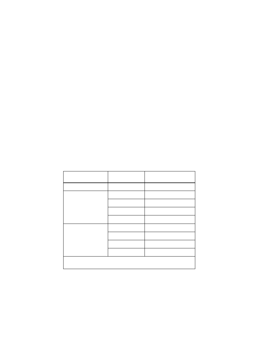
The effect of the analog signal varies depending on mode selected (limited to CI, CP or CV) and
the range (see Table 3-3).
For Master/Slave configurations, the analog programming signal must be simultaneously
applied to all parallel-connected units.
3.16
OPERATOR MAINTENANCE
No scheduled maintenance is required, other than to keep the high current connections tight
and to ensure all airways are clear of obstructions that could cause the load to overheat during
operation at higher power. Calibration Verification should be performed yearly or as required.
The exterior of the load should be cleaned periodically, as is necessary, using a soft cloth damp-
ened with a mild, non-abrasive, water-soluble detergent, and then rinsed with a water-damp-
ened soft cloth.
TABLE 3-3. ANALOG PROGRAMMING CONTROL VOLTAGE SCALE
MODE
RANGE
(SEE NOTE)
ANALOG CONTROL
Constant Current (CI)
Not Applicable
60 Amperes/Volt
Constant
Power
(CP)
100 Volts
6 KWatts/Volt
200 Volts
12 KWatts/Volt
400 Volts
24 KWatts/Volt
800 Volts
48 KWatts/Volt
Constant
Voltage
(CV)
100 Volts
10 Volts/Volt
200 Volts
20 Volts/Volt
400 Volts
40 Volts/Volt
800 Volts
80 Volts/Volt
NOTE: Default voltage measurement setting for CP and CV mode is auto-
range. Use SCPI commands to change ranges (see APPENDIX B).