Figure 4-2. calibration setup for current mode, Calibration setup for current mode -8, Refer to figure 4-2 to connect – KEPCO BOP 1KW-MG Operator Manual, Firmware Ver.3.05 to 4.07 User Manual
Page 140
4-8
BOP-1K 031912
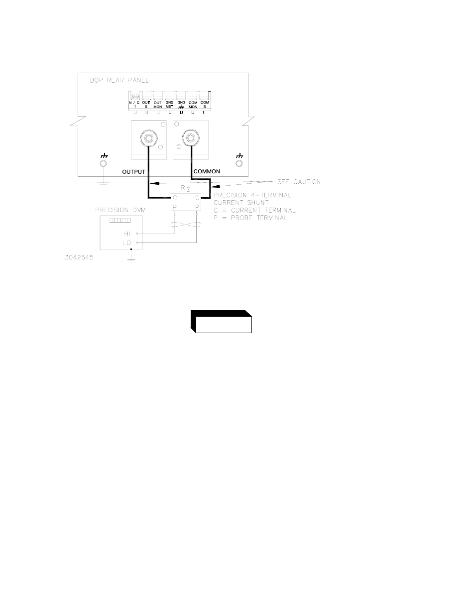
FIGURE 4-2. CALIBRATION SETUP FOR CURRENT MODE
The sense resistor will be dissipating full rated current of the BOP. If
it is hot to the touch, the sense resistor value, power rating and/or
cooling are incorrect; refer to PAR. 4.3 and Table 4-2.
20.Set the BOP to zero volts across the sense resistor (corresponding to zero current) by send-
ing CAL:CURR ZERO. Send CAL:DATA commands as needed (see PAR. 4.3a) until the
reading is as close to zero as possible within the limits specified in Table 4-4 for CURRENT
ZERO.
21.Set the BOP to maximum positive output current by sending CAL:CURR MAX. Measure the
current by reading the voltage across the sense resistor. To adjust, send CAL:DATA com-
mands as needed (see PAR. 4.3b) to adjust the BOP output until the DVM reads as close as
possible above the nominal full scale value within tolerance specified in Table 4-4 for +FULL
SCALE CURRENT.
22.Set the BOP to maximum negative output current by sending CAL:CURR MIN. Continue to
measure the output current of the supply using the DVM connected to the sense resistor. To
adjust, send CAL:DATA commands as needed (see PAR. 4.3b) to adjust the BOP output
until the DVM reads as close as possible above (absolute value) the nominal full scale value
within tolerance specified in Table 4-4 for –FULL SCALE CURRENT.
23.Send CAL:CPR MAX to adjust the maximum positive current protection limit of the power
supply. To adjust, send CAL:DATA commands as needed (see PAR. 4.3c) to adjust the BOP
CAUTION
WIRES BETWEEN BOP OUTPUT AND
SENSE RESISTOR MUST BE RATED TO
CARRY THE RATED OUTPUT
CURRENT OF THE POWER SUPPLY.
AWG#6 IS RECOMMENDED.
WARNING