Figure 17 battery connections – Detcon SmartWireless CXT User Manual
Page 22
Sentinel CXT
Sentinel CXT Instruction Manual
Rev. 1.5
Page 18 of 42
13. Position the battery bracket (and battery) with the connector on the left side, and install the battery
and bracket in the enclosure using the 6-32 screws and hardware removed is step 11. Some wiring
may need to be moved out of the way during this process to ensure that the wiring is not caught
under the bracket.
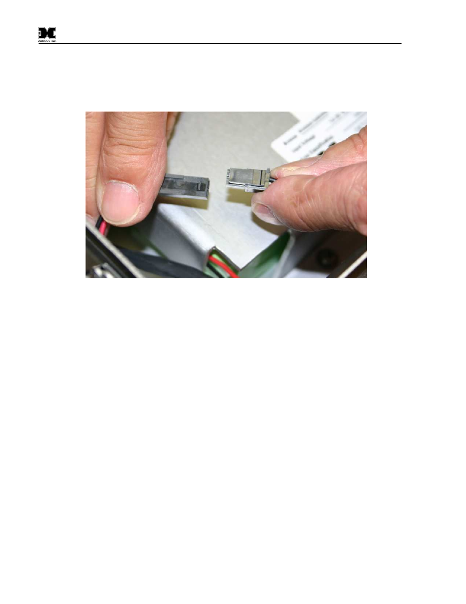
14. Locate the connector mate for the battery connector, and plug the two connectors together.
Figure 17 Battery Connections
15. Re-install the connector to the transceiver (removed in step 10).
16. Cycle power to ensure that the unit powers up. Close the front door panel and screw the front
cover down. The screws should be tightened down to a ‘snug’ fit. These screws do not need to be
tightened down completely, but need to be tightened down enough to give the front door a water
tight seal.
17. Verify normal operation once power is applied to the unit. The unit will cycle through the
following:
•
Boot up and display the company name, model, firmware version and COMM ports available.
•
Proceed to poll Modbus™ addresses of any attached devices.
•
The LCD will then refresh and display the next eight channels and so on until the LCD cycles
back to the first eight channels and repeats the process.
•
The blue fault LED will remain off.