Sensor inputs, 7 sensor inputs – Detcon SmartWireless CXT User Manual
Page 10
Sentinel CXT
Sentinel CXT Instruction Manual
Rev. 1.5
Page 6 of 42
Figure 3
SmartWireless®
CXT Radio Module
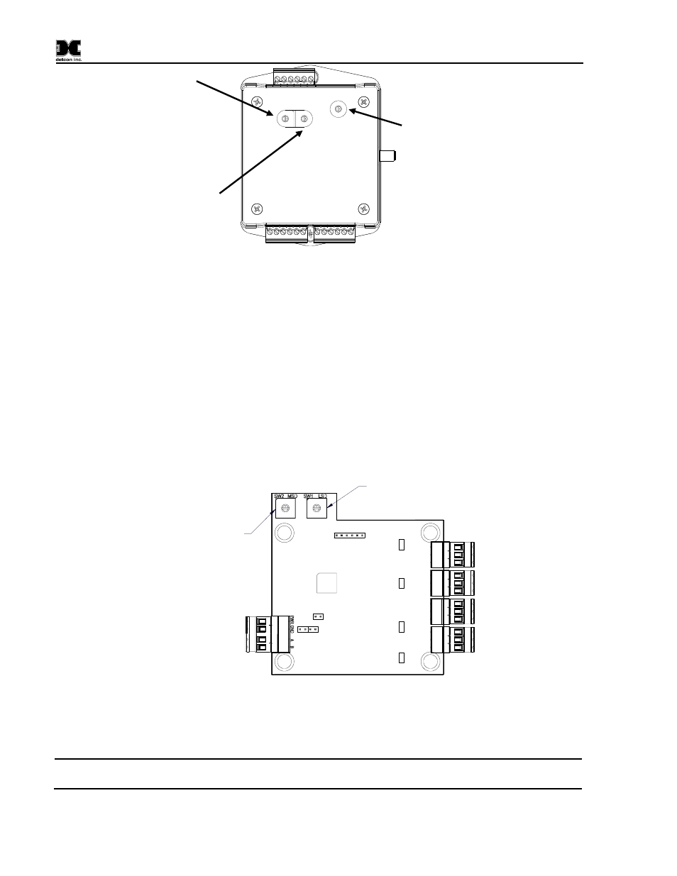
1.7 Sensor Inputs
The SmartWireless® CXT includes a Sensor Input PCA that accepts 4-20mA inputs from up to 4 attached
sensors. The PCA includes two rotary switches to set its Modbus address (Figure 4). This address is set to
01 for SmartWireless® systems using a CXT or Model X40 controller. If an MCX-32 controller is being
used, this address needs to be unique for each CXT in the system. For an MCX-32 system, the addresses
should start at 40h and continue sequentially for each CXT in the system.
Sensor Connector Ratings
Voltage: 9-11.2 VDC
Current: 100 mA max through any single sensor connector
Modbus Address
LSD Switch
Modbus Address
MSD Switch
Figure 4
Sensor Input PCA
Four "quick connects" on the side of the CXT are for sensor connection (Figure 5), supply power to the
sensor from the internal battery and accept the 4-20mA signal from the sensor.
NOTE
Power supplied to the sensors is 11VDC. Any attached sensor must be designed to work at
this voltage level.
RF Channel
Selector Switch
Modbus
Address LSD
Switch
Modbus
Address MSD
Switch