Alarm outputs, 8 alarm outputs, Sensor input connector pin-out – Detcon SmartWireless CXT User Manual
Page 11: Relay pca
Sentinel CXT
Sentinel CXT Instruction Manual
Rev. 1.5
Page 7 of 42
The four sensor input lines are fused at the PC board level for safety purposes. These fuses are not
designed for field replacement and shall not under any circumstances be attempted to be changed out by
anyone but Detcon Factory trained Service personnel.
CAUTION
These PC board mounted fuses are not designed for field replacement and shall not
under any circumstances be attempted to be changed out by anyone but Detcon
Factory-Trained Service personnel.
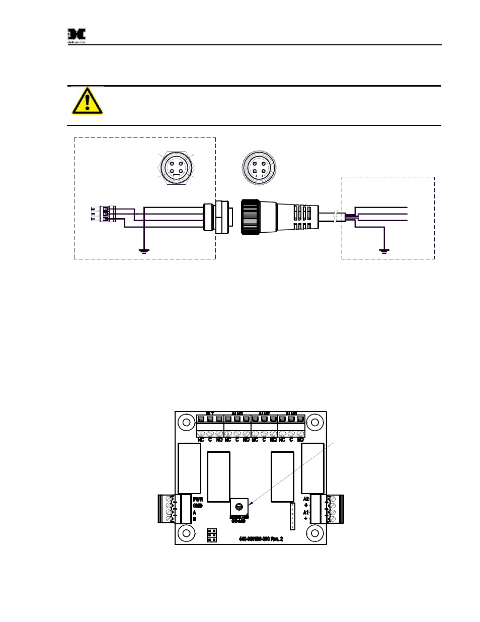
Cable to Sensor 1
(White) 4-20mA
(Red)
PWR
(Black)
GND
(Green) Shld
Sensor
1
4-20mA (White) 2
GND
(Black) 1
PWR
(Red) 3
Sensor Connector
Shld
(Green) 4
1
PCB
Enclosure
1
2
3
4
Figure 5
Sensor Input Connector Pin-out
1.8 Alarm Outputs
The SmartWireless® CXT can optionally include an internal Relay PCA for activating alarm annunciators.
The Relay PCA includes four Class I Division 2 Groups A,B,C,D relays. If the SmartWireless® CXT
includes an attached strobe and/or horn, these devices are also activated by the Relay PCA.
Each Relay PCA must have a unique Modbus address. The Relay PCA includes a single rotary switch to set
its Modbus address (Figure 6). The most significant digit of the address is hard-wired to “8”. The least
significant digit (LSD) is controlled by the rotary switch. The Relay PCA addresses should start at 80h and
continue sequentially for each SmartWireless® CXT in the system.
Internal Alarm
Connections
Modbus
™
Connections
Alarm Relay Connections
Modbus
™
LSD Address
Figure 6
Relay PCA