Local alarm outputs, Figure 4 rd-64x remote display pca (backside), 3 local alarm outputs – Detcon RD-64X-N7 User Manual
Page 8
RD-64X Operators Manual
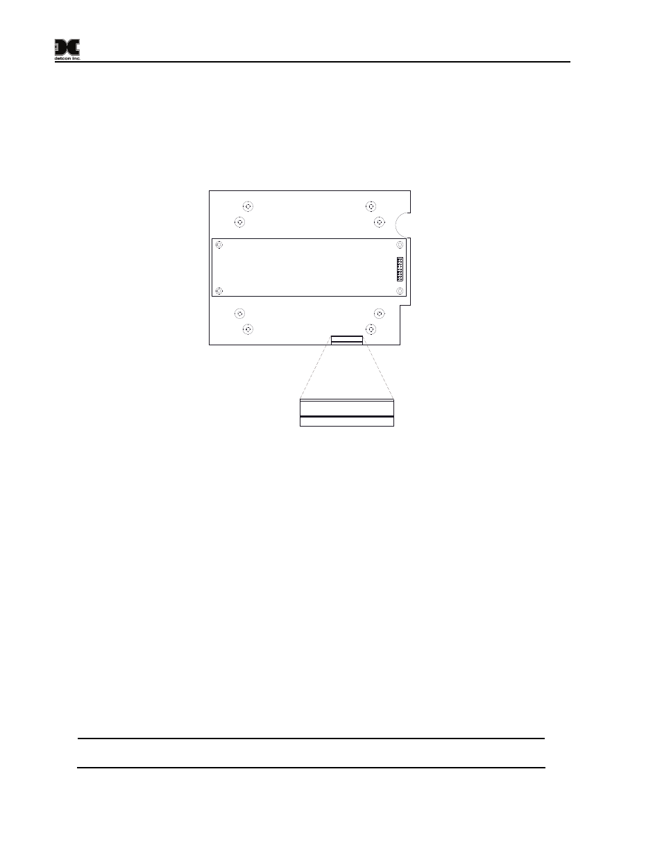
2.3 Local Alarm Outputs
The RD-64X-N4X remote display provides local alarm outputs for up to four alarms (Alarm 1, Alarm 2,
Alarm 3 and Fault) for each of its two defined relay banks (See Figure 4). These local alarm outputs can
drive relays on custom terminal boards provided by Detcon and are controlled by the remote display based
on the configuration and current alarm state of the whole network. They are not intended to drive alarm
devices directly, but rather to drive relay coils (interposing relays) which in turn will drive a higher current
output. The local alarm outputs are open collector and rated for up to 600mA at 40V.
A1
B
1
A2
B
1
A1
B
2
A2
B
2
A3
B
1
FL
T
B
1
A1B1
A2B1
A1B2
A2B2
A3B1
FL
TB
1
A3
B
2
FL
T
B
2
A3B2
FL
TB
2
J10
J10
Figure 4 RD-64X Remote Display PCA (Backside)
A1B1: Alarm 1, Bank1
A1B2: Alarm 1, Bank2
A2B1: Alarm 2, Bank1
A2B2: Alarm 2, Bank2
A3B1: Alarm 3, Bank1
A3B2: Alarm 3, Bank2
FLTB1:
Fault
Alarm,
Bank1 FLTB2:
Fault
Alarm,
Bank2
The local alarm outputs are configured for two separate relay banks (Bank1 and Bank2) and each bank can
support up to four alarm outputs. These local alarm outputs will be triggered whenever a corresponding
alarm is fired that is configured for the outputs specific bank. For example, if alarm 3 of a particular alarm
station configured to Bank2 is triggered, then the local alarm 3 output in Bank2 (A3B2) will also be
triggered. The local alarm outputs do not need to be addressed as they are not part of the Modbus™
network. The banks must, however, be assigned to specific channels via the Set Channel RL4/Alarm
Station Banks menu in section 7.3.8.
When using interposing relays, the customer must protect the RD-64X-N4X local alarm outputs against the
voltage spike that can be over 1000V when the relay is de-energized. This voltage spike will damage the
alarm output since it is well over the rated maximum voltage of 40V and will cause the output to fail. A
transient protection diode (1N4001 or equivalent) can be placed across the relay coil to mitigate the voltage
spike (See Figure 5).
NOTE: External relays used with this circuit must not exceed voltage/current requirements
and must have transient protection to minimize the voltage spike when the coil is de-energized.
Model RD-64X Operators Manual
Rev. 0.1
Page 4 of 30