Figure 11 model rl-4 relay output module – Detcon RD-64X-N7 User Manual
Page 13
RD-64X Operators Manual
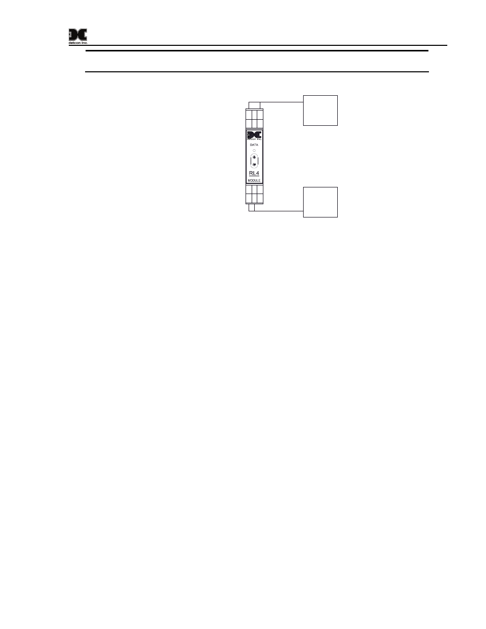
NOTE: The current ratings of the relay contacts should not be exceeded. (5A @ 30VDC, 5A
@ 250VAC)
RELAY
COMM
M
S
D
L
S
D
Alarm 1
Alarm 2
Alarm 3
Fault
Relay 4
Relay 3
Relay 1
Relay 2
There are 4 relay contact
outputs on the RL-4 module.
NC
C
NO
NC
C
NO
C
NC
NO
C
NC
NO
Fault
Device
Alarm 2
Device
Figure 11 Model RL-4 Relay Output Module
The RL-4 module provides contact outputs which are communicated by the remote display to the RL-4
module using RS-485 Modbus™ RTU protocol. Therefore, the RL-4 module must have a unique
Modbus™ address. The module is serially addressed in hex using the two rotary switches on the module’s
front panel labeled MSD (most significant digit) and LSD (least significant digit).
The RD-64X remote display has been configured to have two separate relay banks (Bank1 and Bank2).
Each bank can support up to two RL-4 modules and are defined by addresses 80h-81h for Bank1 and 82h-
83h for Bank2. Anytime a specific alarm is fired for a module in a bank, all corresponding alarms for all
modules in that particular bank are also triggered. For example, if alarm 3 of a particular module is
triggered in Bank2, then all alarm 3’s for all the modules in Bank2 will also be fired. All RL-4 modules
must be setup on the COMM1 (master) port of the remote display and their banks assigned to each active
channel (See section 7.3.8). The RL-4 modules must be addressed according to Table 1 RL-4 Relay
Modbus™ Addresses.
Model RD-64X Operators Manual
Rev. 0.1
Page 9 of 30